Haltech Elite VMS / VMS T pinout
ecurecovery.com/pinouts/haltech/elite-vms · Every pin checked against 2 Haltech documents · data checked 2026-11-01
Haltech Elite VMS / VMS T pinout
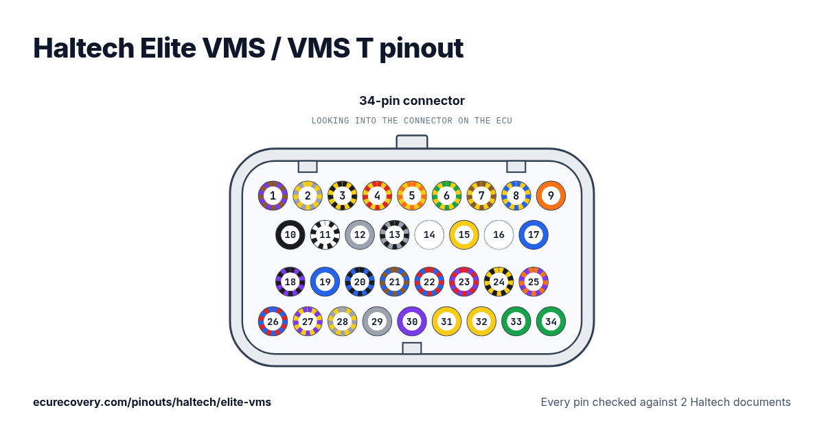
Every pin of the 34-pin connector, with the wire colours of Haltech's harness. Tap a pin to see what it does.
Every pin checked against 2 Haltech documentsPick any pin on the drawing or in the table to see its function, its wire colour and the documents it was checked in.
Haltech Elite VMS / VMS T 34-pin connector pinout
| Pin | Function | Wire |
|---|---|---|
| 1 | DPO 2 | V/BRViolet with brown stripe |
| 2 | AVI 1 | GY/YGrey with yellow stripe |
| 3 | IGN 1 | Y/BYellow with black stripe |
| 4 | IGN 2 | Y/RYellow with red stripe |
| 5 | IGN 3 | Y/OYellow with orange stripe |
| 6 | IGN 4 | Y/GYellow with green stripe |
| 7 | IGN 5 | Y/BRYellow with brown stripe |
| 8 | IGN 6 | Y/LYellow with blue stripe |
| 9 | +5V DC | OOrange |
| 10 | BATTERY GROUND | BBlack |
| 11 | SIGNAL GROUND | B/WBlack with white stripe |
| 12 | DPI 1 | GYGreyShielded |
| 13 | DPI 2 | GY/BGrey with black stripe |
| 14 | AVI 2 | WWhite |
| 15 | AVI 3 | YYellow |
| 16 | CAN H | WWhite |
| 17 | CAN L | LBlue |
| 18 | DPO 1 | V/BViolet with black stripe |
| 19 | DPO 6 | LBlue |
| 20 | DPO 7 | L/BBlue with black stripe |
| 21 | DPO 8 | L/BRBlue with brown stripe |
| 22 | DPO 9 | L/RBlue with red stripe |
| 23 | DPO 3 | V/RViolet with red stripe |
| 24 | DPO 5 | B/YBlack with yellow stripe |
| 25 | DPO 4 | V/OViolet with orange stripe |
| 26 | +13.8V ECU PWR | R/LRed with blue stripe |
| 27 | IGN 7 | Y/VYellow with violet stripe |
| 28 | IGN 8 | Y/GYYellow with grey stripe |
| 29 | AVI 4 | GYGrey |
| 30 | AVI 5 | VViolet |
| 31 | TRIGGER + | YYellow |
| 32 | HOME + | YYellow |
| 33 | TRIGGER - | GGreen |
| 34 | HOME - | GGreen |
Haltech Elite VMS / VMS T pins at a glance
- Which pins are CAN on the Haltech Elite VMS / VMS T?
- CAN H: pin 16 (White, W). CAN L: pin 17 (Blue, L).
- Which pins are the crank and cam inputs on the Haltech Elite VMS / VMS T?
- TRIGGER +: pin 31 (Yellow, Y). HOME +: pin 32 (Yellow, Y). TRIGGER -: pin 33 (Green, G). HOME -: pin 34 (Green, G).
- Which pins are the ignition outputs on the Haltech Elite VMS / VMS T?
- IGN 1: pin 3 (Yellow with black stripe, Y/B). IGN 2: pin 4 (Yellow with red stripe, Y/R). IGN 3: pin 5 (Yellow with orange stripe, Y/O). IGN 4: pin 6 (Yellow with green stripe, Y/G). IGN 5: pin 7 (Yellow with brown stripe, Y/BR). IGN 6: pin 8 (Yellow with blue stripe, Y/L). IGN 7: pin 27 (Yellow with violet stripe, Y/V). IGN 8: pin 28 (Yellow with grey stripe, Y/GY).
- Which pins are ground on the Haltech Elite VMS / VMS T?
- BATTERY GROUND: pin 10 (Black, B). SIGNAL GROUND: pin 11 (Black with white stripe, B/W).
- Which pins power the Haltech Elite VMS / VMS T?
- +13.8V ECU PWR: pin 26 (Red with blue stripe, R/L).
- Which pins are the sensor supplies on the Haltech Elite VMS / VMS T?
- +5V DC: pin 9 (Orange, O).
Haltech Elite VMS / VMS T pinout sheet
A printable sheet with the connector drawings and every pin, made from the checked data on this page.
Where this comes from
Only Haltech's own documents. Pin names and notes are written exactly as Haltech writes them.
Haltech pinout table (support site)
Haltech wiring diagram
Haltech wire colour codes
- B = Black
- BR = Brown
- G = Green
- GY = Grey
- L = Blue
- O = Orange
- R = Red
- V = Violet
- Y = Yellow
- W = White
Two letters: the first is the wire colour, the second is the stripe.
How we checked it
- We start from Haltech's pinout table for this ECU.
- We read every pin again from a second Haltech document, the wiring diagram or the quick start guide. A script compares the two, pin by pin.
- A pin is only shown when its function and its wire colour match in both. Where a diagram has no text to read, we read the pins off the drawing itself.
- The notes are Haltech's own words from its pinout table.
ECU Recovery is not affiliated with Haltech. Haltech and Elite are trademarks of Haltech. If your harness came with its own diagram, check your wiring against it.
More Haltech pinouts
- Haltech Elite 550 pinout
- Haltech Elite 750 pinout
- Haltech Elite 950 pinout
- Haltech Elite 1000 pinout
- Haltech Elite 1500 pinout
- Haltech Elite 2000 pinout
- Haltech Elite 2500 pinout
- Haltech Nexus T1 pinout
- Haltech Nexus T2 pinout
- Haltech Nexus S2 pinout
- Haltech Nexus S3 pinout
- Haltech Nexus R3 pinout
- Haltech Nexus R5 pinout
- Haltech Platinum Sport 1000 pinout
- Haltech Platinum Sport 2000 pinout
- Haltech Platinum Sprint 500 pinout
- Haltech Platinum Sprint RE pinout
- All Haltech pinouts →
Have a Haltech map file? Open it in the free Haltech map viewer.
Map locked with a password?
We unlock Haltech, MaxxECU, LinkECU, Vi-PEC, ECUMaster, Emtron and FuelTech maps. You see proof from your own file first and only pay $159.99 if it works.
Unlock a map