MoTeC M880 pinout
ecurecovery.com/pinouts/motec/m880 · Every pin checked against 2 MoTeC documents · data checked 2026-11-01
MoTeC M880 pinout
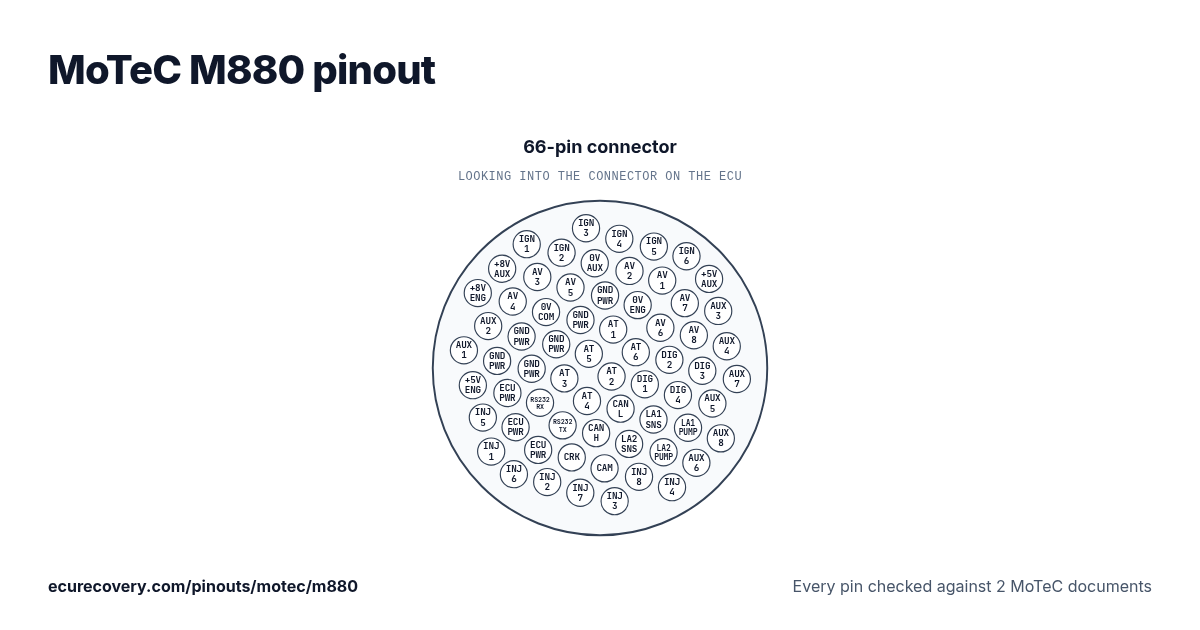
Every pin of the 66-pin connector, with MoTeC's own pin names. Tap a pin to see what it does.
Every pin checked against 2 MoTeC documentsPick any pin on the drawing or in the table to see its function and the documents it was checked in.
MoTeC M880 66-pin connector pinout
| Pin | Function | MoTeC note |
|---|---|---|
| 1 | Ignition Output 1 (IGN1) | Outputs marked * do not have a recirculation diode, see the Output Specifications for more detail. |
| 2 | 8V Auxiliary Sensor and CAN Supply (8V-AUX) | |
| 3 | 8V Engine Sensor Supply (8V-ENG) | |
| 4 | Ignition Output 3 (IGN3) | Outputs marked * do not have a recirculation diode, see the Output Specifications for more detail. |
| 5 | Ignition Output 2 (IGN2) | Outputs marked * do not have a recirculation diode, see the Output Specifications for more detail. |
| 6 | Analog Voltage Input 3 (AV3) | |
| 7 | Analog Voltage Input 4 (AV4) | |
| 8 | Auxiliary Output 2 (AUX2) | |
| 9 | Auxiliary Output 1 (AUX1) | |
| 10 | Ignition Output 4 (IGN4) | Outputs marked * do not have a recirculation diode, see the Output Specifications for more detail. |
| 11 | 0V Auxiliary Sensor Supply (0V-AUX) | |
| 12 | Analog Voltage Input 5 (AV5) | |
| 13 | 0V Comms (0V-COM) | |
| 14 | Battery Negative (GND) | |
| 15 | Battery Negative (GND) | |
| 16 | 5V Engine Sensor Supply (5V-ENG) | |
| 17 | Ignition Output 5 (Not available on M400) (IGN5) | Outputs marked * do not have a recirculation diode, see the Output Specifications for more detail. |
| 18 | Analog Voltage Input 2 (AV2) | |
| 19 | Battery Negative (GND) | |
| 20 | Battery Negative (GND) | |
| 21 | Battery Negative (GND) | |
| 22 | Battery Negative (GND) | |
| 23 | Battery Positive (VBAT) | |
| 24 | Injector Output 5 (Not available on M400) (INJ5) | |
| 25 | Ignition Output 6 (Not available on M400) (IGN6) | Outputs marked * do not have a recirculation diode, see the Output Specifications for more detail. |
| 26 | Analog Voltage Input 1 (AV1) | |
| 27 | 0V Engine Sensor Supply (0V-ENG) | |
| 28 | Analog Temperature Input 1 (AT1) | |
| 29 | Analog Temperature Input 5 (AT5) | |
| 30 | Analog Temperature Input 3 (AT3) | |
| 31 | RS232 Receive Data (RX-232) | |
| 32 | Battery Positive (VBAT) | |
| 33 | Injector Output 1 (INJ1) | |
| 34 | 5V Auxiliary Sensor Supply (5V-AUX) | |
| 35 | Analog Voltage Input 7 (AV7) | |
| 36 | Analog Voltage Input 6 (AV6) | |
| 37 | Analog Temperature Input 6 (AT6) | |
| 38 | Analog Temperature Input 2 (AT2) | |
| 39 | Analog Temperature Input 4 (AT4) | |
| 40 | RS232 Transmit Data (TX-232) | |
| 41 | Battery Positive (VBAT) | |
| 42 | Injector Output 6 (Not available on M400) (INJ6) | |
| 43 | Auxiliary Output 3 (AUX3) | Outputs marked * do not have a recirculation diode, see the Output Specifications for more detail. |
| 44 | Analog Voltage Input 8 (AV8) | |
| 45 | Digital Input 2 (DIG2) | |
| 46 | Digital Input 1 (DIG1) | |
| 47 | Can Bus Low (CAN-LO) | |
| 48 | Can Bus High (CAN-HI) | |
| 49 | Crank Reference Timing Input (REF) | |
| 50 | Injector Output 2 (INJ2) | |
| 51 | Auxiliary Output 4 (AUX4) | Outputs marked * do not have a recirculation diode, see the Output Specifications for more detail. |
| 52 | Digital Input 3 (DIG3) | |
| 53 | Digital Input 4 (DIG4) | |
| 54 | Lambda1 Sense Voltage (LA1-S) | |
| 55 | Lambda2 Sense Voltage (Not available on M400) (LA2-S) | |
| 56 | Cam Sync Timing Input (SYNC) | |
| 57 | Injector Output 7 (Not available on M400 & M600) (INJ7) | |
| 58 | Auxiliary Output 7 (AUX7) | |
| 59 | Auxiliary Output 5 (AUX5) | |
| 60 | Lambda1 Pump Current (LA1-P) | |
| 61 | Lambda2 Pump Current (Not available on M400) (LA2-P) | |
| 62 | Injector Output 8 (Not available on M400 & M600) (INJ8) | |
| 63 | Injector Output 3 (INJ3) | |
| 64 | Auxiliary Output 8 (AUX8) | |
| 65 | Auxiliary Output 6 (AUX6) | |
| 66 | Injector Output 4 (INJ4) |
MoTeC M880 pins at a glance
- Which pins are CAN on the MoTeC M880?
- Can Bus Low (CAN-LO): pin 47. Can Bus High (CAN-HI): pin 48.
- Which pins are the crank and cam inputs on the MoTeC M880?
- Crank Reference Timing Input (REF): pin 49. Cam Sync Timing Input (SYNC): pin 56.
- Which pins are the injector outputs on the MoTeC M880?
- Injector Output 5 (Not available on M400) (INJ5): pin 24. Injector Output 1 (INJ1): pin 33. Injector Output 6 (Not available on M400) (INJ6): pin 42. Injector Output 2 (INJ2): pin 50. Injector Output 7 (Not available on M400 & M600) (INJ7): pin 57. Injector Output 8 (Not available on M400 & M600) (INJ8): pin 62. Injector Output 3 (INJ3): pin 63. Injector Output 4 (INJ4): pin 66.
- Which pins are the ignition outputs on the MoTeC M880?
- Ignition Output 1 (IGN1): pin 1. Ignition Output 3 (IGN3): pin 4. Ignition Output 2 (IGN2): pin 5. Ignition Output 4 (IGN4): pin 10. Ignition Output 5 (Not available on M400) (IGN5): pin 17. Ignition Output 6 (Not available on M400) (IGN6): pin 25.
- Which pins are ground on the MoTeC M880?
- 0V Auxiliary Sensor Supply (0V-AUX): pin 11. 0V Comms (0V-COM): pin 13. Battery Negative (GND): pins 14, 15, 19, 20, 21, 22. 0V Engine Sensor Supply (0V-ENG): pin 27.
- Which pins power the MoTeC M880?
- Battery Positive (VBAT): pins 23, 32, 41.
- Which pins are the sensor supplies on the MoTeC M880?
- 8V Auxiliary Sensor and CAN Supply (8V-AUX): pin 2. 8V Engine Sensor Supply (8V-ENG): pin 3. 5V Engine Sensor Supply (5V-ENG): pin 16. 5V Auxiliary Sensor Supply (5V-AUX): pin 34.
- Which pins are the wideband sensor connections on the MoTeC M880?
- Lambda1 Sense Voltage (LA1-S): pin 54. Lambda2 Sense Voltage (Not available on M400) (LA2-S): pin 55. Lambda1 Pump Current (LA1-P): pin 60. Lambda2 Pump Current (Not available on M400) (LA2-P): pin 61.
MoTeC M880 pinout sheet
A printable sheet with every pin, made from the checked data on this page.
Where this comes from
Only MoTeC's own documents. Pin names and notes are written exactly as MoTeC writes them.
MoTeC user's manual (pin list by function)
MoTeC wiring diagram
Plug drawing: TE Connectivity Deutsch Autosport catalogue, insert arrangements (used for the drawing only)Third party
How we checked it
- We start from the pin list in MoTeC's user's manual for this ECU (Appendix L: Pin list by Function).
- We read every pin again in a second MoTeC document: the ECU's wiring diagram (for the M84, its datasheet). A script compares them pin by pin; where a diagram label sits between two pins, we read it by eye.
- A pin is only shown when both documents name the same function. Pins the manual marks as not available on this model are shown as not used. MoTeC sets no standard wire colours, so none are shown.
- Notes are MoTeC's own words from the manual.
Where MoTeC's documents disagree
20: Appendix L of the manual lists battery negative on pins 14, 15 and 19 only. The M880 wiring diagram, also printed in the manual, draws GND on 14, 15, 19, 20, 21 and 22. We show the diagram's ground.
21: Appendix L of the manual lists battery negative on pins 14, 15 and 19 only. The M880 wiring diagram, also printed in the manual, draws GND on 14, 15, 19, 20, 21 and 22. We show the diagram's ground.
22: Appendix L of the manual lists battery negative on pins 14, 15 and 19 only. The M880 wiring diagram, also printed in the manual, draws GND on 14, 15, 19, 20, 21 and 22. We show the diagram's ground.
ECU Recovery is not affiliated with MoTeC. MoTeC and its product names are trademarks of MoTeC. If your harness came with its own diagram, check your wiring against it.
Map locked with a password?
We unlock Haltech, MaxxECU, LinkECU, Vi-PEC, ECUMaster, Emtron and FuelTech maps. You see proof from your own file first and only pay $159.99 if it works.
Unlock a map