MoTeC M170 pinout
ecurecovery.com/pinouts/motec/m170 · Every pin checked against 3 MoTeC documents · data checked 2026-11-01
MoTeC M170 pinout
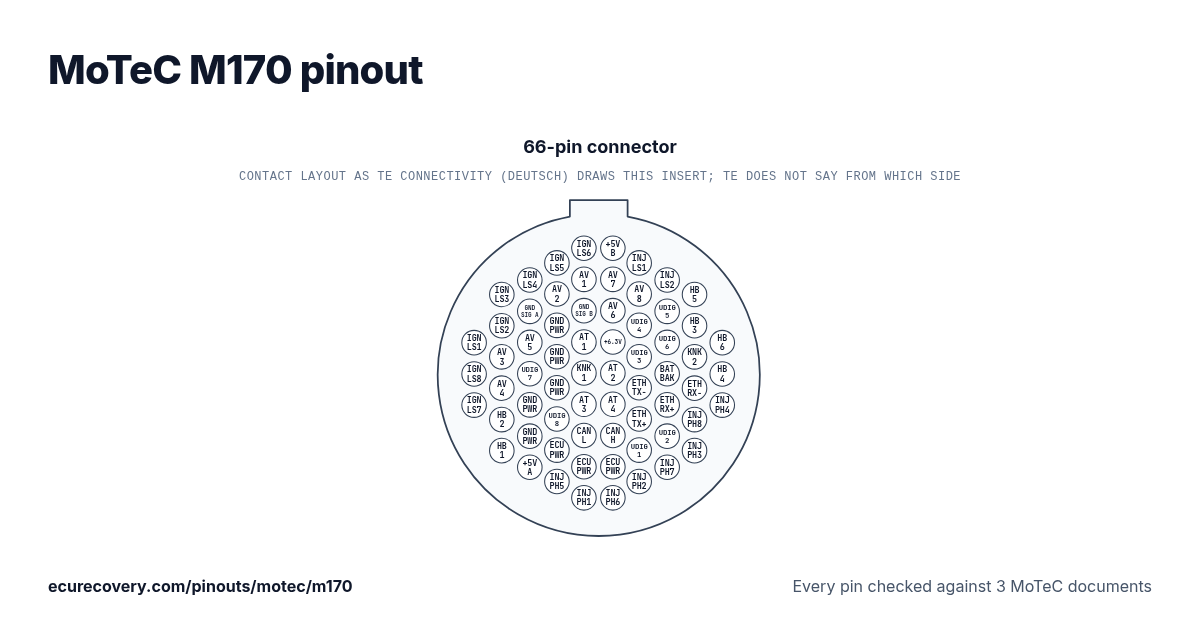
Every pin of the 66-pin connector, with MoTeC's own pin names. Tap a pin to see what it does.
Every pin checked against 3 MoTeC documentsPick any pin on the drawing or in the table to see its function and the documents it was checked in.
MoTeC M170 66-pin connector pinout
Mating connector: Autosport 66 way Red - (Deutsch) AS6-18-35SN – MoTeC #65035
| Pin | Function | MoTeC note |
|---|---|---|
| A01 | Low Side Ignition 1 (IGN_LS1) | |
| A02 | Low Side Ignition 8 (IGN_LS8) | |
| A03 | Low Side Ignition 7 (IGN_LS7) | |
| A04 | Low Side Ignition 3 (IGN_LS3) | |
| A05 | Low Side Ignition 2 (IGN_LS2) | |
| A06 | Analogue Voltage Input 3 (AV3) | |
| A07 | Analogue Voltage Input 4 (AV4) | |
| A08 | Half Bridge Output 2 (OUT_HB2) | |
| A09 | Half Bridge Output 1 (OUT_HB1) | |
| A10 | Low Side Ignition 4 (IGN_LS4) | |
| A11 | Sensor 0V A (SEN_0V_A) | |
| A12 | Analogue Voltage Input 5 (AV5) | |
| A13 | Universal Digital Input 7 (UDIG7) | |
| A14 | Battery Negative (BAT_NEG1) | |
| A15 | Battery Negative (BAT_NEG2) | |
| A16 | Sensor 5.0V A (SEN_5V0_A) | |
| A17 | Low Side Ignition 5 (IGN_LS5) | |
| A18 | Analogue Voltage Input 2 (AV2) | |
| A19 | Battery Negative (BAT_NEG3) | |
| A20 | Battery Negative (BAT_NEG4) | |
| A21 | Battery Negative (BAT_NEG5) | |
| A22 | Universal Digital Input 8 (UDIG8) | |
| A23 | Battery Positive (BAT_POS) | |
| A24 | Peak Hold Injector 5 (INJ_PH5) | |
| A25 | Low Side Ignition 6 (IGN_LS6) | |
| A26 | Analogue Voltage Input 1 (AV1) | |
| A27 | Sensor 0V B (SEN_0V_B) | |
| A28 | Analogue Temperature Input 1 (AT1) | 1k Pull up to SEN_5V_B |
| A29 | Knock Input 1 (KNOCK1) | |
| A30 | Analogue Temperature Input 3 (AT3) | 1k Pull up to SEN_5V_A |
| A31 | CAN Bus 1 Low (CAN_LO) | |
| A32 | Battery Positive (BAT_POS) | |
| A33 | Peak Hold Injector 1 (INJ_PH1) | |
| A34 | Sensor 5.0V B (SEN_5V0_B) | |
| A35 | Analogue Voltage Input 7 (AV7) | |
| A36 | Analogue Voltage Input 6 (AV6) | |
| A37 | Sensor 6.3V (SEN_6V3) | |
| A38 | Analogue Temperature Input 2 (AT2) | 1k Pull up to SEN_5V_B |
| A39 | Analogue Temperature Input 4 (AT4) | 1k Pull up to SEN_5V_A |
| A40 | CAN Bus 1 High (CAN_HI) | |
| A41 | Battery Positive (BAT_POS) | |
| A42 | Peak Hold Injector 6 (INJ_PH6) | |
| A43 | Low Side Injector 1 (INJ_LS1) | |
| A44 | Analogue Voltage Input 8 (AV8) | |
| A45 | Universal Digital Input 4 (UDIG4) | |
| A46 | Universal Digital Input 3 (UDIG3) | |
| A47 | Ethernet Transmit- (ETH_TX-) | Ethernet Green |
| A48 | Ethernet Transmit+ (ETH_TX+) | Ethernet |
| A49 | Universal Digital Input 1 (UDIG1) | |
| A50 | Peak Hold Injector 2 (INJ_PH2) | |
| A51 | Low Side Injector 2 (INJ_LS2) | |
| A52 | Universal Digital Input 5 (UDIG5) | |
| A53 | Universal Digital Input 6 (UDIG6) | |
| A54 | Battery Backup (BAT_BAK) | |
| A55 | Ethernet Receive+ (ETH_RX+) | Ethernet |
| A56 | Universal Digital Input 2 (UDIG2) | |
| A57 | Peak Hold Injector 7 (INJ_PH7) | |
| A58 | Half Bridge Output 5 (OUT_HB5) | |
| A59 | Half Bridge Output 3 (OUT_HB3) | |
| A60 | Knock Input 2 (KNOCK2) | |
| A61 | Ethernet Receive- (ETH_RX-) | Ethernet Orange |
| A62 | Peak Hold Injector 8 (INJ_PH8) | |
| A63 | Peak Hold Injector 3 (INJ_PH3) | |
| A64 | Half Bridge Output 6 (OUT_HB6) | |
| A65 | Half Bridge Output 4 (OUT_HB4) | |
| A66 | Peak Hold Injector 4 (INJ_PH4) |
MoTeC M170 pins at a glance
- Which pins are CAN on the MoTeC M170?
- CAN Bus 1 Low (CAN_LO): pin A31. CAN Bus 1 High (CAN_HI): pin A40.
- Which pins are the injector outputs on the MoTeC M170?
- Peak Hold Injector 5 (INJ_PH5): pin A24. Peak Hold Injector 1 (INJ_PH1): pin A33. Peak Hold Injector 6 (INJ_PH6): pin A42. Low Side Injector 1 (INJ_LS1): pin A43. Peak Hold Injector 2 (INJ_PH2): pin A50. Low Side Injector 2 (INJ_LS2): pin A51. Peak Hold Injector 7 (INJ_PH7): pin A57. Peak Hold Injector 8 (INJ_PH8): pin A62. Peak Hold Injector 3 (INJ_PH3): pin A63. Peak Hold Injector 4 (INJ_PH4): pin A66.
- Which pins are the ignition outputs on the MoTeC M170?
- Low Side Ignition 1 (IGN_LS1): pin A01. Low Side Ignition 8 (IGN_LS8): pin A02. Low Side Ignition 7 (IGN_LS7): pin A03. Low Side Ignition 3 (IGN_LS3): pin A04. Low Side Ignition 2 (IGN_LS2): pin A05. Low Side Ignition 4 (IGN_LS4): pin A10. Low Side Ignition 5 (IGN_LS5): pin A17. Low Side Ignition 6 (IGN_LS6): pin A25.
- Which pins are ground on the MoTeC M170?
- Sensor 0V A (SEN_0V_A): pin A11. Battery Negative (BAT_NEG1): pin A14. Battery Negative (BAT_NEG2): pin A15. Battery Negative (BAT_NEG3): pin A19. Battery Negative (BAT_NEG4): pin A20. Battery Negative (BAT_NEG5): pin A21. Sensor 0V B (SEN_0V_B): pin A27.
- Which pins power the MoTeC M170?
- Battery Positive (BAT_POS): pins A23, A32, A41.
- Which pins are the sensor supplies on the MoTeC M170?
- Sensor 5.0V A (SEN_5V0_A): pin A16. Sensor 5.0V B (SEN_5V0_B): pin A34.
MoTeC M170 pinout sheet
A printable sheet with every pin, made from the checked data on this page.
Where this comes from
Only MoTeC's own documents. Pin names and notes are written exactly as MoTeC writes them.
MoTeC datasheet
MoTeC product page (pinout tables)
MoTeC hardware manual
Plug drawing: TE Connectivity Deutsch Autosport catalogue, insert arrangements (used for the drawing only)Third party
How we checked it
- We start from MoTeC's datasheet for this ECU.
- We read every pin again on MoTeC's product page for the ECU, and in its hardware manual where that covers the ECU. A script compares them, pin by pin.
- A pin is only shown when its pin name and full name match in every document. MoTeC sets no standard wire colours, so none are shown.
- The notes are MoTeC's own words, shown when two of its documents print them alike.
ECU Recovery is not affiliated with MoTeC. MoTeC and its product names are trademarks of MoTeC. If your harness came with its own diagram, check your wiring against it.
Map locked with a password?
We unlock Haltech, MaxxECU, LinkECU, Vi-PEC, ECUMaster, Emtron and FuelTech maps. You see proof from your own file first and only pay $159.99 if it works.
Unlock a map