Link G5 Voodoo Neo6 pinout
ecurecovery.com/pinouts/link-ecu/g5-voodoo-neo6 · Every pin from Link's own guide for this ECU, read twice · data checked 2026-11-01
Link G5 Voodoo Neo6 pinout
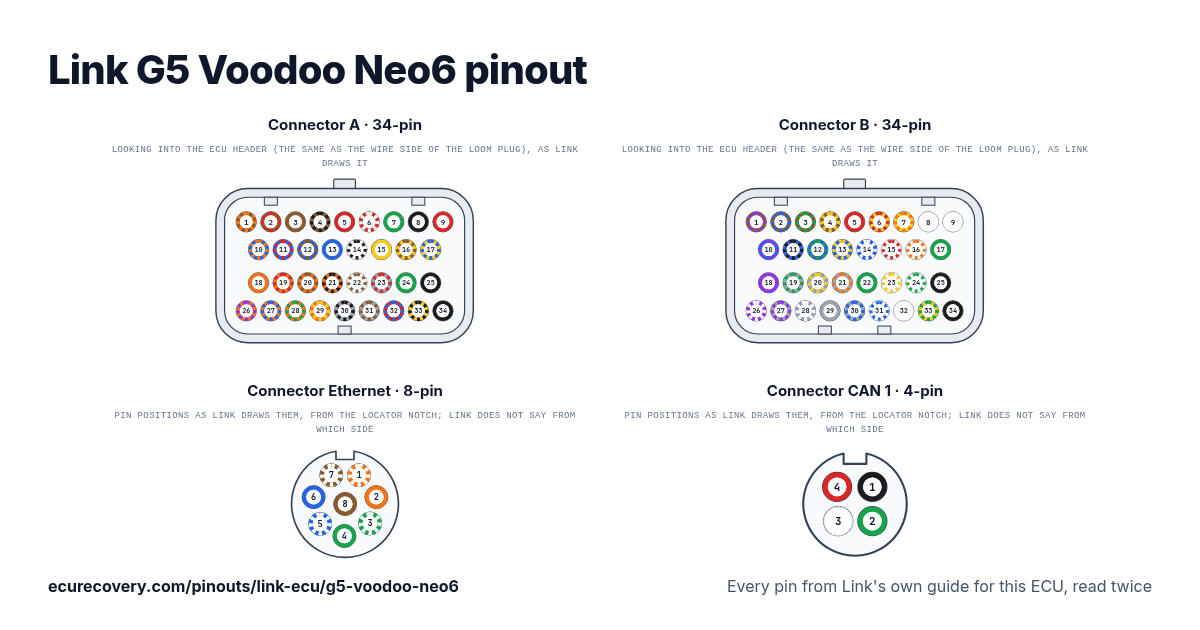
Every pin of the 34-pin A, 34-pin B, 8-pin Ethernet, and 4-pin CAN 1 connectors, with the wire colours of Link's harness. Tap a pin to see what it does.
Every pin from Link's own guide for this ECU, read twicePick any pin on the drawing or in the table to see its function, its wire colour and the documents it was checked in.
Link G5 Voodoo Neo6 connector A pinout (34-pin)
| Pin | Function | Wire | Link note |
|---|---|---|---|
| A1 | Inj 4 | Brown/Orange | |
| A2 | Inj 3 | Brown/Red | |
| A3 | Inj 2 | Brown | |
| A4 | Inj 1 | Brown/Black | |
| A5 | +14V* | Red | Switched or Constant |
| A6 | Ign Sw# | Red/White | Switched Power |
| A7 | Shield Ground | Green | |
| A8 | Trig 1 | Black | |
| A9 | Trig 2 | Red | |
| A10 | Ign 4 | Blue/Orange | |
| A11 | Ign 3 | Blue/Red | |
| A12 | Ign 2 | Blue/Brown | |
| A13 | Ign 1 | Blue | |
| A14 | ADIO 1 | White/Black | |
| A15 | Temp 1 | Yellow | |
| A16 | Temp 2 | Yellow/Brown | |
| A17 | An Volt 1 | Yellow/Blue | |
| A18 | Aux 3 HB 1 | Orange | |
| A19 | Inj 9 DI 7 | Orange/Red | |
| A20 | Aux 2 | Orange/Brown | |
| A21 | Aux 1 | Orange/Black | |
| A22 | An Volt 2 | White/Brown | |
| A23 | DI 3 | Grey/Red | |
| A24 | Sensor Ground | Green | |
| A25 | Ground | Black | |
| A26 | Aux 4 HB 1 | Orange/Purple | |
| A27 | Inj 12 DI 10 | Orange/Blue | |
| A28 | Inj 11 DI 9 | Orange/Green | |
| A29 | Inj 10 DI 8 | Orange/Yellow | |
| A30 | DI 1 | Grey/Black | |
| A31 | DI 2 | Grey/Brown | |
| A32 | +5V | Red/Blue | |
| A33 | An Volt 3 | Yellow/Black | |
| A34 | Ground | Black |
Link G5 Voodoo Neo6 connector B pinout (34-pin)
| Pin | Function | Wire | Link note |
|---|---|---|---|
| B1 | Inj 8 | Brown/Purple | |
| B2 | Inj 7 | Brown/Blue | |
| B3 | Inj 6 | Brown/Green | |
| B4 | Inj 5 | Brown/Yellow | |
| B5 | +14V E-Throttle | Red | |
| B6 | Temp 3 | Yellow/Red | |
| B7 | Temp 4 | Yellow/Orange | |
| B8 | Knock 2 | White | |
| B9 | Knock 1 | White | |
| B10 | Heat | Blue/Purple | |
| B11 | MES | Blue/Black | |
| B12 | Ign 6 | Blue/Green | |
| B13 | Ign 5 | Blue/Yellow | |
| B14 | RE | Blue/White | |
| B15 | ADIO 3 | White/Red | |
| B16 | ADIO 4 | White/Orange | |
| B17 | Shield Ground | Green | |
| B18 | Aux 5 HB 2 | Purple | |
| B19 | DI 6 | Grey/Green | |
| B20 | DI 5 K-Line | Grey/Yellow | |
| B21 | DI 4 | Grey/Orange | |
| B22 | Sensor Ground | Green | |
| B23 | ADIO 5 | White/Yellow | |
| B24 | ADIO 6 | White/Green | |
| B25 | Ground | Black | |
| B26 | Aux 6 HB 2 | Purple/White | |
| B27 | CAN2 High | Grey/Purple | |
| B28 | CAN2 Low | Grey/White | |
| B29 | Ign 8 | Grey | |
| B30 | Ign 7 | Grey/Blue | |
| B31 | IPE | White/Blue | |
| B32 | APE | White | |
| B33 | ADIO 2 | Yellow/Green | |
| B34 | Ground | Black |
Link G5 Voodoo Neo6 connector Ethernet pinout (8-pin)
| Pin | Function | Wire | Link note |
|---|---|---|---|
| ETH-1 | Ethernet | Orange/White | |
| ETH-2 | Ethernet | Orange | |
| ETH-3 | Ethernet | Green/White | |
| ETH-4 | Ethernet | Green | |
| ETH-5 | Ethernet | Blue/White | |
| ETH-6 | Ethernet | Blue | |
| ETH-7 | Ethernet | Brown/White | |
| ETH-8 | Ethernet | Brown |
Link G5 Voodoo Neo6 connector CAN 1 pinout (4-pin)
| Pin | Function | Wire | Link note |
|---|---|---|---|
| CAN-1 | Ground | Black | |
| CAN-2 | CAN Low | Green | |
| CAN-3 | CAN High | White | |
| CAN-4 | Power | Red |
Link G5 Voodoo Neo6 pins at a glance
- Which pins are CAN on the Link G5 Voodoo Neo6?
- CAN2 High: pin B27 (Grey/Purple). CAN2 Low: pin B28 (Grey/White). CAN Low: pin CAN-2 (Green). CAN High: pin CAN-3 (White).
- Which pins are the crank and cam inputs on the Link G5 Voodoo Neo6?
- Trig 1: pin A8 (Black). Trig 2: pin A9 (Red).
- Which pins are the injector outputs on the Link G5 Voodoo Neo6?
- Inj 4: pin A1 (Brown/Orange). Inj 3: pin A2 (Brown/Red). Inj 2: pin A3 (Brown). Inj 1: pin A4 (Brown/Black). Inj 9 DI 7: pin A19 (Orange/Red). Inj 12 DI 10: pin A27 (Orange/Blue). Inj 11 DI 9: pin A28 (Orange/Green). Inj 10 DI 8: pin A29 (Orange/Yellow). Inj 8: pin B1 (Brown/Purple). Inj 7: pin B2 (Brown/Blue). Inj 6: pin B3 (Brown/Green). Inj 5: pin B4 (Brown/Yellow).
- Which pins are the ignition outputs on the Link G5 Voodoo Neo6?
- Ign 4: pin A10 (Blue/Orange). Ign 3: pin A11 (Blue/Red). Ign 2: pin A12 (Blue/Brown). Ign 1: pin A13 (Blue). Ign 6: pin B12 (Blue/Green). Ign 5: pin B13 (Blue/Yellow). Ign 8: pin B29 (Grey). Ign 7: pin B30 (Grey/Blue).
- Which pins are ground on the Link G5 Voodoo Neo6?
- Sensor Ground: pins A24, B22 (Green). Ground: pins A25, A34, B25, B34, CAN-1 (Black).
- Which pins power the Link G5 Voodoo Neo6?
- +14V*: pin A5 (Red). Ign Sw#: pin A6 (Red/White).
- Which pins are the sensor supplies on the Link G5 Voodoo Neo6?
- +5V: pin A32 (Red/Blue).
- Which pins are the wideband sensor connections on the Link G5 Voodoo Neo6?
- Heat: pin B10 (Blue/Purple). MES: pin B11 (Blue/Black). RE: pin B14 (Blue/White). IPE: pin B31 (White/Blue). APE: pin B32 (White).
Link G5 Voodoo Neo6 pinout sheet
A printable sheet with the connector drawings and every pin, made from the checked data on this page.
Where this comes from
Only Link's own documents. Pin names and notes are written exactly as Link writes them.
Link quick start guide for this ECU
Link guide for the G5 Voodoo Neo4, the same pin
Link guide for the G5 Voodoo Pro, the same pin
Link guide for the G5 Voodoo Pro V2, the same pin
Plug drawing: TE Connectivity customer drawing (used for the drawing only)Third party
How we checked it
- Link publishes one pinout document for each ECU: its quick start guide. Every pin here comes from that guide. Link's full wiring manual is only inside its PCLink software, so it is not used.
- A script reads every pin from the guide. Each pin is then read a second time: from Link's guide for a sister ECU that shows the same pin, from the I/O table in the same guide, or by eye from the same guide.
- A pin is only shown when both readings agree on its function and, where Link gives one, its wire colour. Pin numbers are the ones Link prints in its guides.
- Labels, notes and wire colours are written exactly as Link writes them, for example Brown/Orange.
ECU Recovery is not affiliated with Link. Link and its product names are trademarks of Link. If your harness came with its own diagram, check your wiring against it.
More Link pinouts
- Link G5 Voodoo Neo4 pinout
- Link G5 Voodoo Pro pinout
- Link G5 Voodoo Pro V2 pinout
- Link G4X AtomX pinout
- Link G4X MonsoonX pinout
- Link G4X StormX pinout
- Link G4X FuryX pinout
- Link G4X XtremeX pinout
- Link G4+ Atom pinout
- Link G4+ Monsoon pinout
- Link G4+ Storm pinout
- Link G4+ Fury pinout
- Link G4+ Xtreme pinout
- Link G4+ Thunder pinout
- Link G4+ Kurofune pinout
- Link G4+ Force GDI pinout
- All Link pinouts →
Have a Link map file? Open it in the free Link map viewer.
Map locked with a password?
We unlock Haltech, MaxxECU, LinkECU, Vi-PEC, ECUMaster, Emtron and FuelTech maps. You see proof from your own file first and only pay $159.99 if it works.
Unlock a map