FuelTech FT600 pinout
ecurecovery.com/pinouts/fueltech/ft600 · Every pin checked against at least two of 6 FuelTech documents · data checked 2026-11-04
FuelTech FT600 pinout
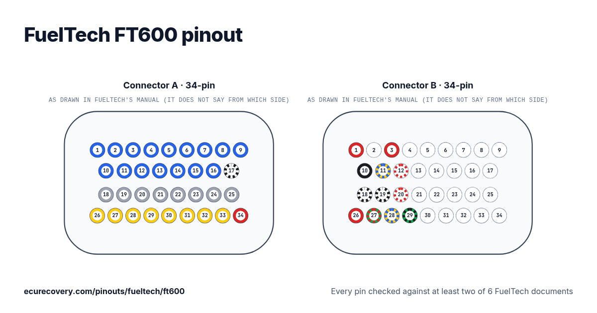
Every pin of the 34-pin A and 34-pin B connectors, with the wire colours of FuelTech's harness. Tap a pin to see what it does.
Every pin checked against at least two of 6 FuelTech documentsPick any pin on the drawing or in the table to see its function, its wire colour and the documents it was checked in.
FuelTech FT600 connector A pinout (34-pin)
| Pin | Function | Wire | FuelTech note |
|---|---|---|---|
| A1 | Blue output #1 | Blue#1Blue | These outputs are usually used for injector control. When needed, they can be configured as auxiliary outputs. |
| A2 | Blue output #2 | Blue#2Blue | These outputs are usually used for injector control. When needed, they can be configured as auxiliary outputs. |
| A3 | Blue output #3 | Blue#3Blue | These outputs are usually used for injector control. When needed, they can be configured as auxiliary outputs. |
| A4 | Blue output #4 | Blue#4Blue | These outputs are usually used for injector control. When needed, they can be configured as auxiliary outputs. |
| A5 | Blue output #5 | Blue#5Blue | These outputs are usually used for injector control. When needed, they can be configured as auxiliary outputs. |
| A6 | Blue output #6 | Blue#6Blue | These outputs are usually used for injector control. When needed, they can be configured as auxiliary outputs. |
| A7 | Blue output #7 | Blue#7Blue | These outputs are usually used for injector control. When needed, they can be configured as auxiliary outputs. |
| A8 | Blue output #8 | Blue#8Blue | These outputs are usually used for injector control. When needed, they can be configured as auxiliary outputs. |
| A9 | Blue output #9 | Blue#9Blue | These outputs are usually used for injector control. When needed, they can be configured as auxiliary outputs. |
| A10 | Blue output #10 | Blue#10Blue | These outputs are usually used for injector control. When needed, they can be configured as auxiliary outputs. |
| A11 | Blue output #11 | Blue#11Blue | These outputs are usually used for injector control. When needed, they can be configured as auxiliary outputs. |
| A12 | Blue output #12 | Blue#12Blue | These outputs are usually used for injector control. When needed, they can be configured as auxiliary outputs. |
| A13 | Blue output #13 | Blue#13Blue | These outputs are usually used for injector control. When needed, they can be configured as auxiliary outputs. |
| A14 | Blue output #14 | Blue#14Blue | These outputs are usually used for injector control. When needed, they can be configured as auxiliary outputs. |
| A15 | Blue output #15 | Blue#15Blue | These outputs are usually used for injector control. When needed, they can be configured as auxiliary outputs. |
| A16 | Blue output #16 | Blue#16Blue | These outputs are usually used for injector control. When needed, they can be configured as auxiliary outputs. |
| A17 | Power ground input | Black/White | Directly wired to the battery negative terminal with no seams. Do not tap any other grounds to this wire, it must run clean straight to the battery negative terminal. |
| A18 | Gray output#1 | Gray#1Grey | These outputs are usually used for ignition control. When needed, they can be set up as injector outputs or auxiliary outputs. By standard, Gray output #8 is used as a tachometer output. |
| A19 | Gray output#2 | Gray#2Grey | These outputs are usually used for ignition control. When needed, they can be set up as injector outputs or auxiliary outputs. By standard, Gray output #8 is used as a tachometer output. |
| A20 | Gray output#3 | Gray#3Grey | These outputs are usually used for ignition control. When needed, they can be set up as injector outputs or auxiliary outputs. By standard, Gray output #8 is used as a tachometer output. |
| A21 | Gray output#4 | Gray#4Grey | These outputs are usually used for ignition control. When needed, they can be set up as injector outputs or auxiliary outputs. By standard, Gray output #8 is used as a tachometer output. |
| A22 | Gray output#5 | Gray#5Grey | These outputs are usually used for ignition control. When needed, they can be set up as injector outputs or auxiliary outputs. By standard, Gray output #8 is used as a tachometer output. |
| A23 | Gray output#6 | Gray#6Grey | These outputs are usually used for ignition control. When needed, they can be set up as injector outputs or auxiliary outputs. By standard, Gray output #8 is used as a tachometer output. |
| A24 | Gray output#7 | Gray#7Grey | These outputs are usually used for ignition control. When needed, they can be set up as injector outputs or auxiliary outputs. By standard, Gray output #8 is used as a tachometer output. |
| A25 | Gray output#8 | Gray#8Grey | These outputs are usually used for ignition control. When needed, they can be set up as injector outputs or auxiliary outputs. By standard, Gray output #8 is used as a tachometer output. |
| A26 | Yellow output#1 | Yellow#1Yellow | Electronic throttle and step motor outputs. Also used as injection or auxiliary outputs (cooling fan, fuel pump, etc.) |
| A27 | Yellow output#2 | Yellow#2Yellow | Electronic throttle and step motor outputs. Also used as injection or auxiliary outputs (cooling fan, fuel pump, etc.) |
| A28 | Yellow output#3 | Yellow#3Yellow | Electronic throttle and step motor outputs. Also used as injection or auxiliary outputs (cooling fan, fuel pump, etc.) |
| A29 | Yellow output#4 | Yellow#4Yellow | Electronic throttle and step motor outputs. Also used as injection or auxiliary outputs (cooling fan, fuel pump, etc.) |
| A30 | Yellow output#5 | Yellow#5Yellow | Electronic throttle and step motor outputs. Also used as injection or auxiliary outputs (cooling fan, fuel pump, etc.) |
| A31 | Yellow output#6 | Yellow#6Yellow | Electronic throttle and step motor outputs. Also used as injection or auxiliary outputs (cooling fan, fuel pump, etc.) |
| A32 | Yellow output#7 | Yellow#7Yellow | Electronic throttle and step motor outputs. Also used as injection or auxiliary outputs (cooling fan, fuel pump, etc.) |
| A33 | Yellow output#8 | Yellow#8Yellow | Electronic throttle and step motor outputs. Also used as injection or auxiliary outputs (cooling fan, fuel pump, etc.) |
| A34 | 12V input from relay | Red | Connected to the pin 87 of the Main Relay. |
FuelTech FT600 connector B pinout (34-pin)
| Pin | Function | Wire | FuelTech note |
|---|---|---|---|
| B1 | RPM signal input | Red | Connected to the crank trigger sensor (hall or magnetic) or to the distributor. To VR sensors, use the shield wire the sensor shield. To Hall sensor, do not use the shield as negative |
| B2 | Magnetic RPM sensor reference | White | Connected to the negative wire of the magnetic sensor. When OEM ECU is reading the sensor in parallel, split this wire with OEM sensor negative - Do not connect when using hall effect sensor. |
| B3 | Cam sync signal input | Red | Connected to the cam sync sensor (hall or magnetic) |
| B4 | Cam sync reference input | White | Connected to the cam sync sensor (hall or magnetic) - Use the shield as negative to the sensor |
| B5 | White input#1 | White#1White | Default: O2 sensor input |
| B6 | White input#2 | White#2White | Default: two-step input |
| B7 | White input#3 | White#3White | Default: Air conditioning button |
| B8 | White input#4 | White#4White | Default: Oil pressure |
| B9 | White input#5 | White#5White | Default: Coolant temperature |
| B10 | Battery negative input | Black | Connected directly to the battery negative with no seams. Do not connect this wire to the chassis, engine block or head. |
| B11 | CAN A LOW | Yellow/Blue | CAN A |
| B12 | CAN A HIGH | White/Red | CAN A |
| B13 | White input#6 | White#6White | Default: fuel pressure |
| B14 | White input#7 | White#7White | Default: Air temperature |
| B15 | White input#8 | White#8White | Default: pedal#2 signal input |
| B16 | White input#9 | White#9White | Default: pedal#1 signal input |
| B17 | White input#10 | White#10White | Default: MAP signal output, electronic throttle 1B input signal |
| B18 | Power ground inputs | Black/White | Directly wired to the battery negative terminal with no seams. Do not tap any other grounds to this wire, it must run clean straight to the battery negative terminal. |
| B19 | Power ground inputs | Black/White | Directly wired to the battery negative terminal with no seams. Do not tap any other grounds to this wire, it must run clean straight to the battery negative terminal. |
| B20 | CAN B HIGH | White/Red | |
| B21 | White input#11 | White#11White | Default: TPS sensor |
| B22 | White input#12 | White#12White | Sensors input |
| B23 | White input#13 | White#13White | Sensors input |
| B24 | White input#14 | White#14White | Sensors input |
| B25 | White input#15 | White#15White | Sensors input |
| B26 | 12V input from relay | Red | Connected to the pin 87 of the Main Relay |
| B27 | 5V outputs for sensors | Green/Red | 5V voltage output for TPS, electronic throttle and pedal sensors |
| B28 | CAN B LOW | Yellow/Blue | |
| B29 | Ground for sensors | Green/Black | Connected the sensors ground |
| B30 | White input#16 | White#16White | Sensors input |
| B31 | White input#17 | White#17White | Sensors input |
| B32 | White input#18 | White#18White | Sensors input |
| B33 | White input#19 | White#19White | Power Shift Input - Blue wire Strain gage sensor (positive signal) |
| B34 | White input#20 | White#20White | Power Shift Input - Orange wire Strain gage sensor (negative signal) |
Locked FuelTech map file? Check it free. You see proof from your own file before you pay anything.
Check my map freeFuelTech FT600 pins at a glance
- Which pins are CAN on the FuelTech FT600?
- CAN A LOW: pin B11 (Yellow/Blue). CAN A HIGH: pin B12 (White/Red). CAN B HIGH: pin B20 (White/Red). CAN B LOW: pin B28 (Yellow/Blue).
- Which pins are the crank and cam inputs on the FuelTech FT600?
- RPM signal input: pin B1 (Red). Magnetic RPM sensor reference: pin B2 (White). Cam sync signal input: pin B3 (Red). Cam sync reference input: pin B4 (White).
- Which pins are the injector outputs on the FuelTech FT600?
- Blue output #1: pin A1 (Blue#1). Blue output #2: pin A2 (Blue#2). Blue output #3: pin A3 (Blue#3). Blue output #4: pin A4 (Blue#4). Blue output #5: pin A5 (Blue#5). Blue output #6: pin A6 (Blue#6). Blue output #7: pin A7 (Blue#7). Blue output #8: pin A8 (Blue#8). Blue output #9: pin A9 (Blue#9). Blue output #10: pin A10 (Blue#10). Blue output #11: pin A11 (Blue#11). Blue output #12: pin A12 (Blue#12). Blue output #13: pin A13 (Blue#13). Blue output #14: pin A14 (Blue#14). Blue output #15: pin A15 (Blue#15). Blue output #16: pin A16 (Blue#16).
- Which pins are the ignition outputs on the FuelTech FT600?
- Gray output#1: pin A18 (Gray#1). Gray output#2: pin A19 (Gray#2). Gray output#3: pin A20 (Gray#3). Gray output#4: pin A21 (Gray#4). Gray output#5: pin A22 (Gray#5). Gray output#6: pin A23 (Gray#6). Gray output#7: pin A24 (Gray#7). Gray output#8: pin A25 (Gray#8).
- Which pins are ground on the FuelTech FT600?
- Power ground input: pin A17 (Black/White). Power ground inputs: pins B18, B19 (Black/White).
- Which pins power the FuelTech FT600?
- 12V input from relay: pins A34, B26 (Red).
- Which pins are the sensor supplies on the FuelTech FT600?
- 5V outputs for sensors: pin B27 (Green/Red).
FuelTech FT600 pinout sheet
A printable sheet with the connector drawings and every pin, made from the checked data on this page.
Where this comes from
Only FuelTech's own documents. Pin names and notes are written exactly as FuelTech writes them.
FuelTech FT450 / FT550 / FT550LITE / FT600 manual
FuelTech PRO600 wiring harness manual (GEN-1)
FuelTech PRO600 wiring harness manual (GEN-2)
FuelTech FT700 / FT700PLUS complete manual (written for the FT700: the same pins)
FuelTech FT700 quick reference (written for the FT700: the same pins)
FuelTech PRO600 GEN III wiring harness manual
How we checked it
- We start from the pin table in FuelTech's manual for this ECU: pin, wire colour and function.
- Every pin is read again in a second FuelTech document: its harness manuals, which list each ECU pin with its wire colour, or for the FT700 its quick reference. A script compares them pin by pin.
- A pin is only shown when the second document gives the same wire colour and function. FuelTech names its general-purpose wires by colour and number (Blue #1 is blue output 1), so the number has to match too.
- Labels, notes and wire colours are written exactly as FuelTech writes them.
Where FuelTech's documents disagree
B18: FuelTech's PRO600 harness manuals (GEN-1, GEN-2 and GEN III) list this wire as Black, to the battery negative. The FT600 manual, and the FT700 manual and quick reference, list it as Black/White power ground. Shown: Black/White, as in the ECU manuals.
B19: FuelTech's PRO600 harness manuals (GEN-1, GEN-2 and GEN III) list this wire as Black, to the battery negative. The FT600 manual, and the FT700 manual and quick reference, list it as Black/White power ground. Shown: Black/White, as in the ECU manuals.
ECU Recovery is not affiliated with FuelTech. FuelTech and its product names are trademarks of FuelTech. If your harness came with its own diagram, check your wiring against it.
Map locked with a password?
We unlock Haltech, MaxxECU, LinkECU, Vi-PEC, ECUMaster, Emtron and FuelTech maps. You see proof from your own file first and only pay $159.99 if it works.
Unlock a map