ECUMaster EMU PRO 16 pinout
ecurecovery.com/pinouts/ecumaster/emu-pro-16 · Every pin from ECUMaster's own pinout for this ECU, read twice · data checked 2026-11-01
ECUMaster EMU PRO 16 pinout
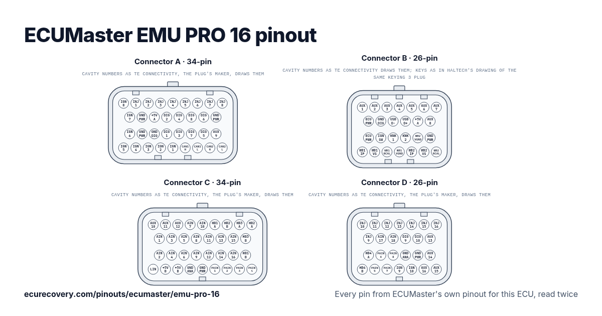
Every pin of the 34-pin A, 26-pin B, 34-pin C, and 26-pin D connectors, with ECUMaster's own pin names. Tap a pin to see what it does.
Every pin from ECUMaster's own pinout for this ECU, read twicePick any pin on the drawing or in the table to see its function and the documents it was checked in.
ECUMaster EMU PRO 16 connector A pinout (34-pin)
Mating connector: TE AMP Superseal 1.0 4-1437290-1
| Pin | Function | ECUMaster note |
|---|---|---|
| A1 | Ignition 8 | Output for active or passive ignition coils. |
| A2 | Injector 1 | Output for high or low impedance injectors. |
| A3 | Injector 2 | Output for high or low impedance injectors. |
| A4 | Injector 3 | Output for high or low impedance injectors. |
| A5 | Injector 4 | Output for high or low impedance injectors. |
| A6 | Injector 5 | Output for high or low impedance injectors. |
| A7 | Injector 6 | Output for high or low impedance injectors. |
| A8 | Injector 7 | Output for high or low impedance injectors. |
| A9 | Injector 8 | Output for high or low impedance injectors. |
| A10 | Ignition 7 | Output for active or passive ignition coils. |
| A11 | Power GND | Power ground. |
| A12 | +5V source A | +5V sensor supply, source A. |
| A13 | Digital 2 | Digital signal input. |
| A14 | Digital 4 | Digital signal input. |
| A15 | Digital 8 | Digital signal input. |
| A16 | Digital 6 (turbo) | Digital signal input, can be used for turboshaft speed sensor. |
| A17 | Power GND | Power ground. |
| A18 | Ignition 6 | Output for active or passive ignition coils. |
| A19 | Power GND | Power ground. |
| A20 | Digital GND | Digital ground. |
| A21 | Digital 1 (crank) | Digital signal input, dedicated crankshaft sensor input. |
| A22 | Digital 3 | Digital signal input. |
| A23 | Digital 7 | Digital signal input. |
| A24 | Digital 5 (turbo) | Digital signal input, can be used for turboshaft speed sensor. |
| A25 | Auxiliary 9 | Output for auxiliary devices. |
| A26 | Ignition 5 | Output for active or passive ignition coils. |
| A27 | Ignition 4 | Output for active or passive ignition coils. |
| A28 | Ignition 3 | Output for active or passive ignition coils. |
| A29 | Ignition 2 | Output for active or passive ignition coils. |
| A30 | Ignition 1 | Output for active or passive ignition coils. |
| A31 | CAN 1 high (PC comm) | CAN bus, fixed 1Mbps, used for communication with PC and peripheral devices. |
| A32 | CAN 1 low (PC comm) | CAN bus, fixed 1Mbps, used for communication with PC and peripheral devices. |
| A33 | CAN 2 high | CAN bus, configurable speed, used for communication with peripheral devices. |
| A34 | CAN 2 low | CAN bus, configurable speed, used for communication with peripheral devices. |
ECUMaster EMU PRO 16 connector B pinout (26-pin)
Mating connector: TE AMP Superseal 1.0 1473416-1
| Pin | Function | ECUMaster note |
|---|---|---|
| B1 | Auxiliary 1 (WBO heater) | Output for auxiliary devices, can be used as a WBO heater. |
| B2 | Auxiliary 2 (WBO heater) | Output for auxiliary devices, can be used as a WBO heater. |
| B3 | Auxiliary 3 (WBO heater) | Output for auxiliary devices, can be used as a WBO heater. |
| B4 | Auxiliary 4 (WBO heater) | Output for auxiliary devices, can be used as a WBO heater. |
| B5 | Auxiliary 5 | Output for auxiliary devices. |
| B6 | Auxiliary 6 | Output for auxiliary devices. |
| B7 | Auxiliary 7 | Output for auxiliary devices. |
| B8 | +12V supply | Power supply for the ECU and H-bridges. |
| B9 | Digital GND (flash drive) | Digital ground, recommended for flash drive connection. |
| B10 | USB D- (flash drive) | USB data pin for a flash drive, data logging. |
| B11 | USB D+ (flash drive) | USB data pin for a flash drive, data logging. |
| B12 | +5V source A (flash drive) | +5V sensor supply, source A, recommended for flash drive connection. |
| B13 | Auxiliary 8 | Output for auxiliary devices. |
| B14 | +12V supply | Power supply for the ECU and H-bridges. |
| B15 | +12V switched | +12V input to switch the ECU on or off. |
| B16 | Knock sensor 1 | Knock sensor input. |
| B17 | Knock sensor 2 | Knock sensor input. |
| B18 | WBO 2 VGND (LSU 4.9) | Wideband oxygen sensor input, LSU 4.9 Pin 2 (IPN / VM). |
| B19 | Power GND | Power ground. |
| B20 | WBO 1 IP (LSU 4.9) | Wideband oxygen sensor input, LSU 4.9 Pin 1 (APE / IP). |
| B21 | WBO 1 VS (LSU 4.9) | Wideband oxygen sensor input, LSU 4.9 Pin 6 (UN / RE). |
| B22 | WBO 1 RCAL (LSU 4.9) | Wideband oxygen sensor input, LSU 4.9 Pin 5 (RT / IA). |
| B23 | WBO 1 VGND (LSU 4.9) | Wideband oxygen sensor input, LSU 4.9 Pin 2 (IPN / VM). |
| B24 | WBO 2 IP (LSU 4.9) | Wideband oxygen sensor input, LSU 4.9 Pin 1 (APE / IP). |
| B25 | WBO 2 VS (LSU 4.9) | Wideband oxygen sensor input, LSU 4.9 Pin 6 (UN / RE). |
| B26 | WBO 2 RCAL (LSU 4.9) | Wideband oxygen sensor input, LSU 4.9 Pin 5 (RT / IA). |
ECUMaster EMU PRO 16 connector C pinout (34-pin)
Mating connector: TE AMP Superseal 1.0 4-1437290-0
| Pin | Function | ECUMaster note |
|---|---|---|
| C1 | Auxiliary 10 | Output for auxiliary devices. |
| C2 | Auxiliary 11 | Output for auxiliary devices. |
| C3 | Auxiliary 12 | Output for auxiliary devices. |
| C4 | Analog 7 | Analog signal input. |
| C5 | Analog 10 (2k2 pull) | Analog signal input. |
| C6 | H-bridge 1A | H-bridge output. |
| C7 | H-bridge 2B | H-bridge output. |
| C8 | H-bridge 3A | H-bridge output. |
| C9 | H-bridge 2A | H-bridge output. |
| C10 | Analog 1 (MAP) | Analog signal input, dedicated MAP sensor input. |
| C11 | Analog 3 | Analog signal input. |
| C12 | Analog 5 | Analog signal input. |
| C13 | Analog 8 | Analog signal input. |
| C14 | Analog 11 (2k2 pull) | Analog signal input. |
| C15 | Analog 13 (1k pull) | Analog signal input. |
| C16 | Analog 15 (330R pull) | Analog signal input. |
| C17 | H-bridge 3B | H-bridge output. |
| C18 | Analog 2 | Analog signal input. |
| C19 | Analog 4 | Analog signal input. |
| C20 | Analog 6 | Analog signal input. |
| C21 | Analog 9 (2k2 pull) | Analog signal input. |
| C22 | Analog 12 (2k2 pull) | Analog signal input. |
| C23 | Analog 14 (1k pull) | Analog signal input. |
| C24 | Analog 16 (100R pull) | Analog signal input. |
| C25 | H-bridge 1B | H-bridge output. |
| C26 | LIN | LIN network. |
| C27 | +5V source B | +5V sensor supply, source B. |
| C28 | +5V source B | +5V sensor supply, source B. |
| C29 | Analog GND | Analog ground. |
| C30 | Power GND | Power ground. |
| C31 | Precision analog 1 | High precision analog input. |
| C32 | Precision analog 2 | High precision analog input. |
| C33 | Precision analog 3 | High precision analog input. |
| C34 | Precision analog 4 | High precision analog input. |
ECUMaster EMU PRO 16 connector D pinout (26-pin)
Mating connector: TE AMP Superseal 1.0 3-1437290-7
| Pin | Function | ECUMaster note |
|---|---|---|
| D1 | Injector 10 | Output for high or low impedance injectors. |
| D2 | Injector 11 | Output for high or low impedance injectors. |
| D3 | Injector 12 | Output for high or low impedance injectors. |
| D4 | Injector 13 | Output for high or low impedance injectors. |
| D5 | Injector 14 | Output for high or low impedance injectors. |
| D6 | Injector 15 | Output for high or low impedance injectors. |
| D7 | Injector 16 | Output for high or low impedance injectors. |
| D8 | Injector 9 | Output for high or low impedance injectors. |
| D9 | Analog 17 | Analog signal input. |
| D10 | Analog 18 | Analog signal input. |
| D11 | Digital 9 / Analog 19 | Digital signal input or Analog signal input. |
| D12 | Digital 10 / Analog 20 | Digital signal input or Analog signal input. |
| D13 | Auxiliary 13 | Output for auxiliary devices. |
| D14 | H-bridge 4A | H-bridge output. |
| D15 | Precision analog 6 | High precision analog input. |
| D16 | Precision analog 8 | High precision analog input. |
| D17 | Analog GND | Analog ground. |
| D18 | Power GND | Power ground. |
| D19 | Auxiliary 14 | Output for auxiliary devices. |
| D20 | H-bridge 4B | H-bridge output. |
| D21 | Precision analog 5 | High precision analog input. |
| D22 | Precision analog 7 | High precision analog input. |
| D23 | Ignition 9 | Output for active or passive ignition coils. |
| D24 | Ignition 10 | Output for active or passive ignition coils. |
| D25 | Auxiliary 16 | Output for auxiliary devices. |
| D26 | Auxiliary 15 | Output for auxiliary devices. |
ECUMaster EMU PRO 16 pins at a glance
- Which pins are CAN on the ECUMaster EMU PRO 16?
- CAN 1 high (PC comm): pin A31. CAN 1 low (PC comm): pin A32. CAN 2 high: pin A33. CAN 2 low: pin A34.
- Which pins are the injector outputs on the ECUMaster EMU PRO 16?
- Injector 1: pin A2. Injector 2: pin A3. Injector 3: pin A4. Injector 4: pin A5. Injector 5: pin A6. Injector 6: pin A7. Injector 7: pin A8. Injector 8: pin A9. Injector 10: pin D1. Injector 11: pin D2. Injector 12: pin D3. Injector 13: pin D4. Injector 14: pin D5. Injector 15: pin D6. Injector 16: pin D7. Injector 9: pin D8.
- Which pins are the ignition outputs on the ECUMaster EMU PRO 16?
- Ignition 8: pin A1. Ignition 7: pin A10. Ignition 6: pin A18. Ignition 5: pin A26. Ignition 4: pin A27. Ignition 3: pin A28. Ignition 2: pin A29. Ignition 1: pin A30. Ignition 9: pin D23. Ignition 10: pin D24.
- Which pins are ground on the ECUMaster EMU PRO 16?
- Power GND: pins A11, A17, A19, B19, C30, D18. Digital GND: pin A20. Digital GND (flash drive): pin B9. Analog GND: pins C29, D17.
- Which pins power the ECUMaster EMU PRO 16?
- +12V supply: pins B8, B14. +12V switched: pin B15.
- Which pins are the sensor supplies on the ECUMaster EMU PRO 16?
- +5V source A: pin A12. +5V source A (flash drive): pin B12. +5V source B: pins C27, C28.
- Which pins are the wideband sensor connections on the ECUMaster EMU PRO 16?
- WBO 2 VGND (LSU 4.9): pin B18. WBO 1 IP (LSU 4.9): pin B20. WBO 1 VS (LSU 4.9): pin B21. WBO 1 RCAL (LSU 4.9): pin B22. WBO 1 VGND (LSU 4.9): pin B23. WBO 2 IP (LSU 4.9): pin B24. WBO 2 VS (LSU 4.9): pin B25. WBO 2 RCAL (LSU 4.9): pin B26.
ECUMaster EMU PRO 16 pinout sheet
A printable sheet with every pin, made from the checked data on this page.
Where this comes from
Only ECUMaster's own documents. Pin names and notes are written exactly as ECUMaster writes them.
ECUMaster pinout for this ECU
ECUMaster guide for the EMU PRO 8, the same pin
Plug drawing: TE Connectivity customer drawing (used for the drawing only)Third party
How we checked it
- We start from ECUMaster's pinout document for this ECU.
- Every pin is read again in a second ECUMaster document: the compact pinout sheet, the user manual or, for pins that are the same on a sister ECU, that ECU's pinout. Where no second document lists a pin, we read it a second time by eye from the same pinout.
- A pin is only shown when both readings give the same function. ECUMaster's documents name no wire colours, so none are shown.
- Notes are ECUMaster's own descriptions from its pinout.
ECU Recovery is not affiliated with ECUMaster. ECUMaster and its product names are trademarks of ECUMaster. If your harness came with its own diagram, check your wiring against it.
Map locked with a password?
We unlock Haltech, MaxxECU, LinkECU, Vi-PEC, ECUMaster, Emtron and FuelTech maps. You see proof from your own file first and only pay $159.99 if it works.
Unlock a map