Pinagem da FuelTech FT700
ecurecovery.com/pinouts/fueltech/ft700 · Cada pino conferido em 2 documentos da FuelTech · dados conferidos em 2026-11-04
Pinagem da FuelTech FT700
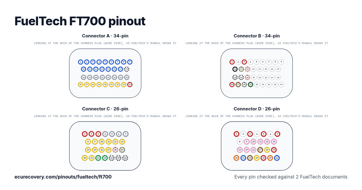
Cada pino dos conectores A (34 pinos), B (34 pinos), C (26 pinos) e D (26 pinos), com as cores dos fios do chicote da FuelTech. Toque em um pino para ver o que ele faz.
Cada pino conferido em 2 documentos da FuelTechEscolha qualquer pino no desenho ou na tabela para ver a função, a cor do fio e os documentos em que foi conferido.
FuelTech FT700: pinagem do conector A (34 pinos)
| Pino | Função | Fio | Nota da FuelTech |
|---|---|---|---|
| A1 | Blue output #01 | Blue#01Azul | These outputs are usually used for injector control. When needed, they can be configured as auxiliary outputs. |
| A2 | Blue output #02 | Blue#02Azul | These outputs are usually used for injector control. When needed, they can be configured as auxiliary outputs. |
| A3 | Blue output #03 | Blue#03Azul | These outputs are usually used for injector control. When needed, they can be configured as auxiliary outputs. |
| A4 | Blue output #04 | Blue#04Azul | These outputs are usually used for injector control. When needed, they can be configured as auxiliary outputs. |
| A5 | Blue output #05 | Blue#05Azul | These outputs are usually used for injector control. When needed, they can be configured as auxiliary outputs. |
| A6 | Blue output #06 | Blue#06Azul | These outputs are usually used for injector control. When needed, they can be configured as auxiliary outputs. |
| A7 | Blue output #07 | Blue#07Azul | These outputs are usually used for injector control. When needed, they can be configured as auxiliary outputs. |
| A8 | Blue output #08 | Blue#08Azul | These outputs are usually used for injector control. When needed, they can be configured as auxiliary outputs. |
| A9 | Blue output #09 | Blue#09Azul | These outputs are usually used for injector control. When needed, they can be configured as auxiliary outputs. |
| A10 | Blue output #10 | Blue#10Azul | These outputs are usually used for injector control. When needed, they can be configured as auxiliary outputs. |
| A11 | Blue output #11 | Blue#11Azul | These outputs are usually used for injector control. When needed, they can be configured as auxiliary outputs. |
| A12 | Blue output #12 | Blue#12Azul | These outputs are usually used for injector control. When needed, they can be configured as auxiliary outputs. |
| A13 | Blue output #13 | Blue#13Azul | These outputs are usually used for injector control. When needed, they can be configured as auxiliary outputs. |
| A14 | Blue output #14 | Blue#14Azul | These outputs are usually used for injector control. When needed, they can be configured as auxiliary outputs. |
| A15 | Blue output #15 | Blue#15Azul | These outputs are usually used for injector control. When needed, they can be configured as auxiliary outputs. |
| A16 | Blue output #16 | Blue#16Azul | These outputs are usually used for injector control. When needed, they can be configured as auxiliary outputs. |
| A17 | Power ground | Black/WhitePreto/branco | Directly wired to the battery negative terminal with no seams. Do not tap any other grounds to this wire, it must run clean straight to the battery negative terminal. |
| A18 | Gray output#01 | Gray#01Cinza | These outputs are usually used for ignition control. When needed, they can be set up as injector outputs (Peak and Hold driver required) By standard, Gray output #08 is used as a tachometer output. |
| A19 | Gray output#02 | Gray#02Cinza | These outputs are usually used for ignition control. When needed, they can be set up as injector outputs (Peak and Hold driver required) By standard, Gray output #08 is used as a tachometer output. |
| A20 | Gray output#03 | Gray#03Cinza | These outputs are usually used for ignition control. When needed, they can be set up as injector outputs (Peak and Hold driver required) By standard, Gray output #08 is used as a tachometer output. |
| A21 | Gray output#04 | Gray#04Cinza | These outputs are usually used for ignition control. When needed, they can be set up as injector outputs (Peak and Hold driver required) By standard, Gray output #08 is used as a tachometer output. |
| A22 | Gray output#05 | Gray#05Cinza | These outputs are usually used for ignition control. When needed, they can be set up as injector outputs (Peak and Hold driver required) By standard, Gray output #08 is used as a tachometer output. |
| A23 | Gray output#06 | Gray#06Cinza | These outputs are usually used for ignition control. When needed, they can be set up as injector outputs (Peak and Hold driver required) By standard, Gray output #08 is used as a tachometer output. |
| A24 | Gray output#07 | Gray#07Cinza | These outputs are usually used for ignition control. When needed, they can be set up as injector outputs (Peak and Hold driver required) By standard, Gray output #08 is used as a tachometer output. |
| A25 | Gray output#08 | Gray#08Cinza | These outputs are usually used for ignition control. When needed, they can be set up as injector outputs (Peak and Hold driver required) By standard, Gray output #08 is used as a tachometer output. |
| A26 | Yellow output#01 | Yellow#01Amarelo | Electronic throttle and step motor outputs. Also used as injection or auxiliary outputs (cooling fan, fuel pump, etc.) |
| A27 | Yellow output#02 | Yellow#02Amarelo | Electronic throttle and step motor outputs. Also used as injection or auxiliary outputs (cooling fan, fuel pump, etc.) |
| A28 | Yellow output#03 | Yellow#03Amarelo | Electronic throttle and step motor outputs. Also used as injection or auxiliary outputs (cooling fan, fuel pump, etc.) |
| A29 | Yellow output#04 | Yellow#04Amarelo | Electronic throttle and step motor outputs. Also used as injection or auxiliary outputs (cooling fan, fuel pump, etc.) |
| A30 | Yellow output#05 | Yellow#05Amarelo | Electronic throttle and step motor outputs. Also used as injection or auxiliary outputs (cooling fan, fuel pump, etc.) |
| A31 | Yellow output#06 | Yellow#06Amarelo | Electronic throttle and step motor outputs. Also used as injection or auxiliary outputs (cooling fan, fuel pump, etc.) |
| A32 | Yellow output#07 | Yellow#07Amarelo | Electronic throttle and step motor outputs. Also used as injection or auxiliary outputs (cooling fan, fuel pump, etc.) |
| A33 | Yellow output#08 | Yellow#08Amarelo | Electronic throttle and step motor outputs. Also used as injection or auxiliary outputs (cooling fan, fuel pump, etc.) |
| A34 | 12V input from relay | RedVermelho | Connected to the pin 87 of the Main Relay. |
FuelTech FT700: pinagem do conector B (34 pinos)
| Pino | Função | Fio | Nota da FuelTech |
|---|---|---|---|
| B1 | RPM signal input | RedVermelho | Connected to the crank trigger sensor (hall or magnetic) or to the distributor. |
| B2 | Magnetic RPM sensor reference | WhiteBranco | Connected to the negative wire of the magnetic sensor, split the wire with OEM reference sensor - Do not connect when using hall effect sensor. |
| B3 | Cam sync signal input | RedVermelho | Connected to the cam sync sensor (hall or magnetic) |
| B4 | Cam sync reference input | WhiteBranco | Connected to the negative wire of the magnetic sensor. When OEM ECU is reading the sensor in parallel, split this wire with OEM sensor negative - Do not use the shield as negative to the sensor |
| B5 | White input#01 * | White#01Branco | Default: O2 sensor input |
| B6 | White input#02 * | White#02Branco | Default: two-step input |
| B7 | White input#03 * | White#03Branco | Default: Air conditioning button |
| B8 | White input#04 * | White#04Branco | Default: Oil pressure |
| B9 | White input#05 * | White#05Branco | Default: Coolant temperature |
| B10 | Battery negative | BlackPreto | Connected directly to the battery negative with no seams. Do not connect this wire to the chassis, engine block or head. |
| B11 | CAN A LOW | Yellow/BlueAmarelo/azul | CAN A |
| B12 | CAN A HIGH | White/RedBranco/vermelho | CAN A |
| B13 | White input#06 * | White#06Branco | Default: fuel pressure |
| B14 | White input#07 * | White#07Branco | Default: Air temperature |
| B15 | White input#08 * | White#08Branco | Default: pedal#2 signal input |
| B16 | White input#09 * | White#09Branco | Default: pedal#1 signal input |
| B17 | White input#10 * | White#10Branco | Default: MAP signal output, electronic throttle 1B input signal |
| B18 | Power ground | Black/WhitePreto/branco | Directly wired to the battery negative terminal with no seams. Do not tap any other grounds to this wire, it must run clean straight to the battery negative terminal. |
| B19 | Power ground | Black/WhitePreto/branco | Directly wired to the battery negative terminal with no seams. Do not tap any other grounds to this wire, it must run clean straight to the battery negative terminal. |
| B20 | CAN B HIGH | White/RedBranco/vermelho | |
| B21 | White input#11 * | White#11Branco | Default: TPS sensor |
| B22 | White input#12 | White#12Branco | Generic sensor input |
| B23 | White input#13 | White#13Branco | Generic sensor input |
| B24 | White input#14 | White#14Branco | Generic sensor input |
| B25 | White input#15 | White#15Branco | Generic sensor input |
| B26 | 12V input from relay | RedVermelho | Connected to the pin 87 of the Main Relay |
| B27 | 5V outputs for sensors | Green/RedVerde/vermelho | 5V voltage output for TPS, electronic throttle and pedal sensors |
| B28 | CAN B LOW | Yellow/BlueAmarelo/azul | |
| B29 | Ground for sensors | Green/BlackVerde/preto | Connected the sensors ground |
| B30 | White input#16 | White#16Branco | Generic sensor input |
| B31 | White input#17 | White#17Branco | Generic sensor input |
| B32 | White input#18 | White#18Branco | Generic sensor input |
| B33 | White input#19 | White#19Branco | Strain gauge input - Blue wire Strain gage sensor (positive signal) |
| B34 | White input#20 | White#20Branco | Strain gauge input - Orange wire Strain gage sensor (negative signal) |
FuelTech FT700: pinagem do conector C (26 pinos)
| Pino | Função | Fio | Nota da FuelTech |
|---|---|---|---|
| C1 | 12V input from relay | RedVermelho | Connected to the pin 87 of the Main Relay |
| C2 | 12V input from relay | RedVermelho | Connected to the pin 87 of the Main Relay |
| C3 | 12V input from relay | RedVermelho | Connected to the pin 87 of the Main Relay |
| C4 | Gray output #09 | Gray #09Cinza | These outputs are usually used for ignition control. When needed, they can be set up as injector outputs or auxiliary outputs. |
| C5 | Gray output #10 | Gray #10Cinza | These outputs are usually used for ignition control. When needed, they can be set up as injector outputs or auxiliary outputs. |
| C6 | Gray output #11 | Gray #11Cinza | These outputs are usually used for ignition control. When needed, they can be set up as injector outputs or auxiliary outputs. |
| C7 | Gray output #12 | Gray #12Cinza | These outputs are usually used for ignition control. When needed, they can be set up as injector outputs or auxiliary outputs. |
| C8 | Yellow output #09 | Yellow #09Amarelo | Electronic throttle and step motor outputs. Also used as injection or auxiliary outputs (cooling fan, fuel pump, etc.) |
| C9 | Yellow output #10 | Yellow #10Amarelo | Electronic throttle and step motor outputs. Also used as injection or auxiliary outputs (cooling fan, fuel pump, etc.) |
| C10 | Yellow output #11 | Yellow #11Amarelo | Electronic throttle and step motor outputs. Also used as injection or auxiliary outputs (cooling fan, fuel pump, etc.) |
| C11 | Yellow output #12 | Yellow #12Amarelo | Electronic throttle and step motor outputs. Also used as injection or auxiliary outputs (cooling fan, fuel pump, etc.) |
| C12 | Yellow output #13 | Yellow #13Amarelo | Electronic throttle and step motor outputs. Also used as injection or auxiliary outputs (cooling fan, fuel pump, etc.) |
| C13 | Yellow output #14 | Yellow #14Amarelo | Electronic throttle and step motor outputs. Also used as injection or auxiliary outputs (cooling fan, fuel pump, etc.) |
| C14 | Yellow output #15 | Yellow #15Amarelo | Electronic throttle and step motor outputs. Also used as injection or auxiliary outputs (cooling fan, fuel pump, etc.) |
| C15 | Yellow output #16 | Yellow #16Amarelo | Electronic throttle and step motor outputs. Also used as injection or auxiliary outputs (cooling fan, fuel pump, etc.) |
| C16 | Yellow output #17 | Yellow #17Amarelo | Electronic throttle and step motor outputs. Also used as injection or auxiliary outputs (cooling fan, fuel pump, etc.) |
| C17 | Yellow output #18 | Yellow #18Amarelo | Electronic throttle and step motor outputs. Also used as injection or auxiliary outputs (cooling fan, fuel pump, etc.) |
| C18 | CAN C (+) | White/RedBranco/vermelho | CAN C |
| C19 | CAN C (-) | Blue/YellowAzul/amarelo | CAN C |
| C20 | Yellow output #19 | Yellow #19Amarelo | Electronic throttle and step motor outputs. Also used as injection or auxiliary outputs (cooling fan, fuel pump, etc.) |
| C21 | Yellow output #20 | Yellow #20Amarelo | Electronic throttle and step motor outputs. Also used as injection or auxiliary outputs (cooling fan, fuel pump, etc.) |
| C22 | Heat positive O2 sensor | GreenVerde | Power supply for O2 sensor heaters 1 and 2 ***. |
| C23 | Heat positive O2 sensor | GreenVerde | Power supply for O2 sensor heaters 1 and 2 ***. |
| C24 | Power ground | Black/WhitePreto/branco | Directly wired to the battery negative terminal with no seams. Do not tap any other grounds to this wire, it must run clean straight to the battery negative terminal. |
| C25 | Power ground | Black/WhitePreto/branco | Directly wired to the battery negative terminal with no seams. Do not tap any other grounds to this wire, it must run clean straight to the battery negative terminal. |
| C26 | Power ground | Black/WhitePreto/branco | Directly wired to the battery negative terminal with no seams. Do not tap any other grounds to this wire, it must run clean straight to the battery negative terminal. |
FuelTech FT700: pinagem do conector D (26 pinos)
| Pino | Função | Fio | Nota da FuelTech |
|---|---|---|---|
| D1 | Input frequency channel #01 | RedVermelho | Shielded cable for reading RPM and speed signals - Frequency #01 |
| D2 | Input frequency channel #01 | WhiteBranco | Shielded cable for reading RPM and speed signals - Frequency #01 |
| D3 | Input frequency channel #02 | RedVermelho | Shielded cable for reading RPM and speed signals - Frequency #02 |
| D4 | Input frequency channel #02 | WhiteBranco | Shielded cable for reading RPM and speed signals - Frequency #02 |
| D5 | Input frequency channel #03 | RedVermelho | Shielded cable for reading RPM and speed signals - Frequency #03 |
| D6 | Input frequency channel #03 | WhiteBranco | Shielded cable for reading RPM and speed signals - Frequency #03 |
| D7 | Input frequency channel #04 | RedVermelho | Shielded cable for reading RPM and speed signals - Frequency #04 |
| D8 | Input frequency channel #04 | WhiteBranco | Shielded cable for reading RPM and speed signals - Frequency #04 |
| D9 | Input for high speed reading #01 | Pink #01Rosa | Used for high speed sensors (400khz per channel) |
| D10 | Input for high speed reading #02 | Pink #02Rosa | Used for high speed sensors (400khz per channel) |
| D11 | Input for high speed reading #03 | Pink #03Rosa | Used for high speed sensors (400khz per channel) |
| D12 | Input for high speed reading #04 | Pink #04Rosa | Used for high speed sensors (400khz per channel) |
| D13 | Input for high speed reading #05 | Pink #05Rosa | Used for high speed sensors (400khz per channel) |
| D14 | Input for high speed reading #06 | Pink #06Rosa | Used for high speed sensors (400khz per channel) |
| D15 | Input for high speed reading #07 | Pink #07Rosa | Used for high speed sensors (400khz per channel) |
| D16 | Input for high speed reading #08 | Pink #08Rosa | Used for high speed sensors (400khz per channel) |
| D17 | Signal | BrownMarrom | Connected O2 sensor #1 NOTE: The Heat positive signal sensor is in connector C, green wire (pin 22) |
| D18 | Ground | YellowAmarelo | Connected O2 sensor #1 NOTE: The Heat positive signal sensor is in connector C, green wire (pin 22) |
| D19 | IP | RedVermelho | Connected O2 sensor #1 NOTE: The Heat positive signal sensor is in connector C, green wire (pin 22) |
| D20 | Resistor calibration | OrangeLaranja | Connected O2 sensor #1 NOTE: The Heat positive signal sensor is in connector C, green wire (pin 22) |
| D21 | Heater negative | BlueAzul | Connected O2 sensor #1 NOTE: The Heat positive signal sensor is in connector C, green wire (pin 22) |
| D22 | Signal | BrownMarrom | Connected O2 sensor #2 NOTE: The Heat positive signal sensor is in connector C, green wire (pin 23) |
| D23 | Ground | YellowAmarelo | Connected O2 sensor #2 NOTE: The Heat positive signal sensor is in connector C, green wire (pin 23) |
| D24 | IP | RedVermelho | Connected O2 sensor #2 NOTE: The Heat positive signal sensor is in connector C, green wire (pin 23) |
| D25 | Resistor calibration | OrangeLaranja | Connected O2 sensor #2 NOTE: The Heat positive signal sensor is in connector C, green wire (pin 23) |
| D26 | Heater negative | BlueAzul | Connected O2 sensor #2 NOTE: The Heat positive signal sensor is in connector C, green wire (pin 23) |
Arquivo de mapa FuelTech bloqueado? Verifique grátis. Você vê a prova do seu próprio arquivo antes de pagar qualquer coisa.
Verificar meu mapa grátisPinos da FuelTech FT700 em resumo
- Quais pinos são CAN na FuelTech FT700?
- CAN A LOW: pino B11 (Yellow/Blue). CAN A HIGH: pino B12 (White/Red). CAN B HIGH: pino B20 (White/Red). CAN B LOW: pino B28 (Yellow/Blue). CAN C (+): pino C18 (White/Red). CAN C (-): pino C19 (Blue/Yellow).
- Quais pinos são as entradas de virabrequim e comando na FuelTech FT700?
- RPM signal input: pino B1 (Red). Magnetic RPM sensor reference: pino B2 (White). Cam sync signal input: pino B3 (Red). Cam sync reference input: pino B4 (White).
- Quais pinos são as saídas de injetores na FuelTech FT700?
- Blue output #01: pino A1 (Blue#01). Blue output #02: pino A2 (Blue#02). Blue output #03: pino A3 (Blue#03). Blue output #04: pino A4 (Blue#04). Blue output #05: pino A5 (Blue#05). Blue output #06: pino A6 (Blue#06). Blue output #07: pino A7 (Blue#07). Blue output #08: pino A8 (Blue#08). Blue output #09: pino A9 (Blue#09). Blue output #10: pino A10 (Blue#10). Blue output #11: pino A11 (Blue#11). Blue output #12: pino A12 (Blue#12). Blue output #13: pino A13 (Blue#13). Blue output #14: pino A14 (Blue#14). Blue output #15: pino A15 (Blue#15). Blue output #16: pino A16 (Blue#16).
- Quais pinos são as saídas de ignição na FuelTech FT700?
- Gray output#01: pino A18 (Gray#01). Gray output#02: pino A19 (Gray#02). Gray output#03: pino A20 (Gray#03). Gray output#04: pino A21 (Gray#04). Gray output#05: pino A22 (Gray#05). Gray output#06: pino A23 (Gray#06). Gray output#07: pino A24 (Gray#07). Gray output#08: pino A25 (Gray#08). Gray output #09: pino C4 (Gray #09). Gray output #10: pino C5 (Gray #10). Gray output #11: pino C6 (Gray #11). Gray output #12: pino C7 (Gray #12).
- Quais pinos são terra na FuelTech FT700?
- Power ground: pinos A17, B18, B19, C24, C25, C26 (Black/White).
- Quais pinos alimentam a FuelTech FT700?
- 12V input from relay: pinos A34, B26, C1, C2, C3 (Red).
- Quais pinos alimentam os sensores na FuelTech FT700?
- 5V outputs for sensors: pino B27 (Green/Red).
- Quais pinos são as ligações do sensor de banda larga na FuelTech FT700?
- Heat positive O2 sensor: pinos C22, C23 (Green). Signal: pinos D17, D22 (Brown). Ground: pinos D18, D23 (Yellow). IP: pinos D19, D24 (Red). Resistor calibration: pinos D20, D25 (Orange). Heater negative: pinos D21, D26 (Blue).
Folha de pinagem da FuelTech FT700
Uma folha para imprimir com os desenhos dos conectores e cada pino, feita com os dados conferidos desta página.
De onde vem
Só documentos da própria FuelTech. Os nomes dos pinos e as notas aparecem exatamente como a FuelTech escreve, em inglês.
Manual completo da FuelTech FT700 / FT700PLUS
Referência rápida da FuelTech FT700
Manual do chicote PRO600 GEN III da FuelTech
Como conferimos
- Partimos da tabela de pinos do manual da FuelTech para esta ECU: pino, cor do fio e função.
- Cada pino é lido de novo em um segundo documento da FuelTech: os manuais de chicote, que listam cada pino da ECU com a cor do fio, ou na FT700 a referência rápida. Um script compara pino a pino.
- Um pino só aparece quando o segundo documento traz a mesma cor de fio e a mesma função. A FuelTech nomeia os fios de uso geral por cor e número (Blue #1 é a saída azul 1), então o número também precisa bater.
- Rótulos, notas e cores dos fios estão escritos exatamente como a FuelTech escreve.
Onde os documentos da FuelTech discordam
B18: o manual do chicote PRO600 GEN III da FuelTech (para a FT600 e a FT700) indica este fio como preto, ao negativo da bateria. O manual e a referência rápida da FT700 indicam preto/branco, terra de potência. Mostrado: preto/branco, como nos documentos da própria ECU.
B19: o manual do chicote PRO600 GEN III da FuelTech (para a FT600 e a FT700) indica este fio como preto, ao negativo da bateria. O manual e a referência rápida da FT700 indicam preto/branco, terra de potência. Mostrado: preto/branco, como nos documentos da própria ECU.
A ECU Recovery não tem vínculo com a FuelTech. FuelTech e os nomes dos seus produtos são marcas da FuelTech. Se o seu chicote veio com um diagrama próprio, confira a sua ligação com ele.
Mapa bloqueado com senha?
Desbloqueamos mapas Haltech, MaxxECU, LinkECU, Vi-PEC, ECUMaster, Emtron e FuelTech. Primeiro você vê uma prova do seu próprio arquivo e só paga $159.99 se funcionar.
Desbloquear um mapa