Pinagem da FuelTech FT550
ecurecovery.com/pinouts/fueltech/ft550 · Cada pino conferido em pelo menos dois de 4 documentos da FuelTech · dados conferidos em 2026-11-04
Pinagem da FuelTech FT550
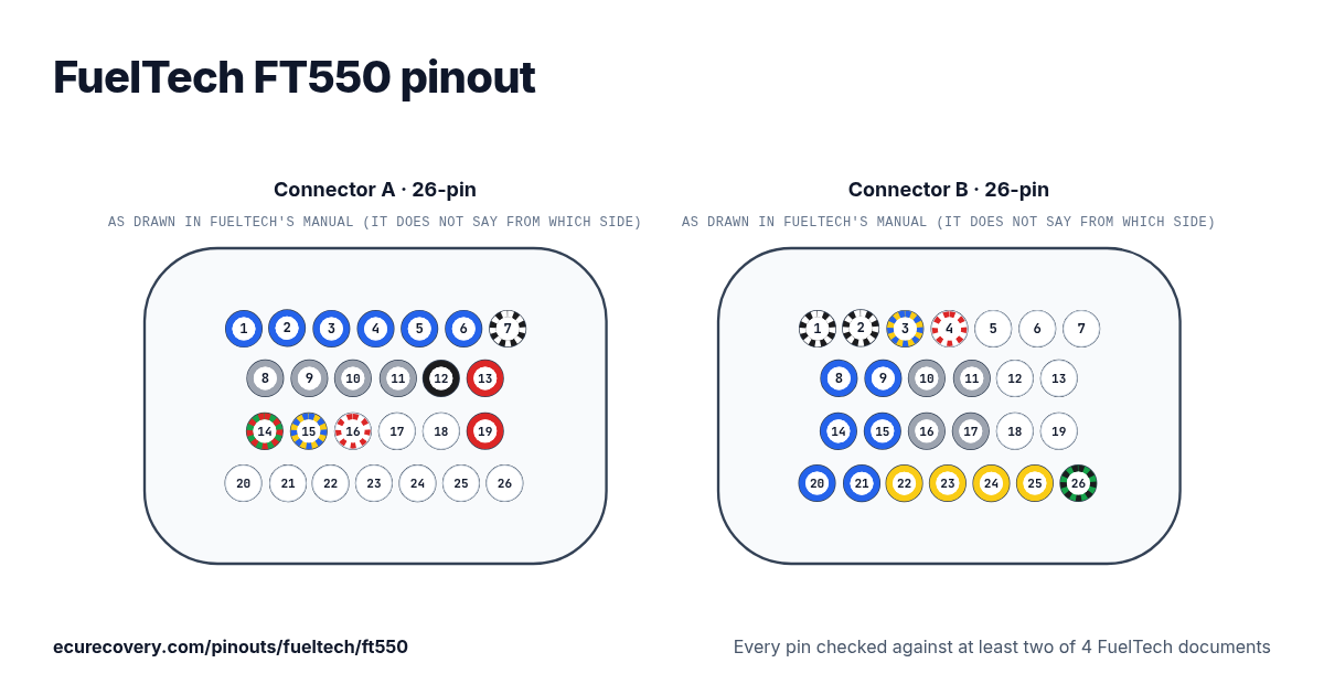
Cada pino do conector A de 26 pinos e do B de 26 pinos, com as cores dos fios do chicote da FuelTech. Toque em um pino para ver o que ele faz.
Cada pino conferido em pelo menos dois de 4 documentos da FuelTechEscolha qualquer pino no desenho ou na tabela para ver a função, a cor do fio e os documentos em que foi conferido.
FuelTech FT550: pinagem do conector A (26 pinos)
| Pino | Função | Fio | Nota da FuelTech |
|---|---|---|---|
| A1 | Blue output #1 | Blue #1Azul | These outputs are usually used for injector control. When needed, they can be configured as auxiliary outputs. |
| A2 | Blue output #2 | Blue #2Azul | These outputs are usually used for injector control. When needed, they can be configured as auxiliary outputs. |
| A3 | Blue output #3 | Blue #3Azul | These outputs are usually used for injector control. When needed, they can be configured as auxiliary outputs. |
| A4 | Blue output #4 | Blue #4Azul | These outputs are usually used for injector control. When needed, they can be configured as auxiliary outputs. |
| A5 | Blue output #5 | Blue #5Azul | These outputs are usually used for injector control. When needed, they can be configured as auxiliary outputs. |
| A6 | Blue output #6 | Blue #6Azul | These outputs are usually used for injector control. When needed, they can be configured as auxiliary outputs. |
| A7 | Power ground input | Black/whitePreto/branco | Directly wired to the battery negative terminal with no seams. Do not tap any other grounds to this wire, it must run clean straight to the battery negative terminal. |
| A8 | Gray output #1 | Gray #1Cinza | These outputs are usually used for ignition control. When needed, they can be set up as injector outputs or auxiliary outputs. |
| A9 | Gray output #2 | Gray #2Cinza | These outputs are usually used for ignition control. When needed, they can be set up as injector outputs or auxiliary outputs. |
| A10 | Gray output #3 | Gray #3Cinza | These outputs are usually used for ignition control. When needed, they can be set up as injector outputs or auxiliary outputs. |
| A11 | Gray output #4 | Gray #4Cinza | These outputs are usually used for ignition control. When needed, they can be set up as injector outputs or auxiliary outputs. |
| A12 | Battery negative input | BlackPreto | Connected directly to the battery negative with no seams. Do not connect this wire to the chassis, engine block or head. |
| A13 | 12V input from relay | RedVermelho | Connected to the pin 87 of the Main Relay |
| A14 | 5V outputs for sensors | Green/RedVerde/vermelho | 5V voltage output for TPS, electronic throttle and pedal sensors |
| A15 | CAN A (-) | Yellow/BlueAmarelo/azul | |
| A16 | CAN A (+) | White/RedBranco/vermelho | |
| A17 | CAM sync signal input | Shielded Cable (white)BrancoBlindado | Connected to the cam sync sensor (hall or magnetic) |
| A18 | Magnetic RPM sensor reference | Black Shielded Cable (White)BrancoBlindado | Connected to the negative wire of the magnetic sensor. When OEM ECU is reading the sensor in parallel, split this wire with OEM sensor negative - Do not connect when using hall effect sensor. |
| A19 | RPM signal input | Black Shielded Cable (Red)VermelhoBlindado | Connected to the crank trigger sensor (hall or magnetic) or to the distributor. To VR sensors, use the shield wire the sensor shield. To Hall sensor, do not use the shield as negative |
| A20 | Input #1 | White #1Branco | Sensors input |
| A21 | Input #2 | White #2Branco | Sensors input |
| A22 | Input #3 | White #3Branco | Sensors input |
| A23 | Input #4 | White #4Branco | Sensors input |
| A24 | Input #5 | White #5Branco | Sensors input |
| A25 | Input #6 | White #6Branco | Sensors input |
| A26 | Input #7 | White #7Branco | Sensors input |
FuelTech FT550: pinagem do conector B (26 pinos)
| Pino | Função | Fio | Nota da FuelTech |
|---|---|---|---|
| B1 | Power ground inputs | Black/WhitePreto/branco | Directly wired to the battery negative terminal with no seams. Do not tap any other grounds to this wire, it must run clean straight to the battery negative terminal. |
| B2 | Power ground inputs | Black/WhitePreto/branco | Directly wired to the battery negative terminal with no seams. Do not tap any other grounds to this wire, it must run clean straight to the battery negative terminal. |
| B3 | CAN B (-) | Yellow/BlueAmarelo/azul | |
| B4 | CAN B (+) | White/RedBranco/vermelho | |
| B5 | Input #8 | White #8Branco | Sensors input |
| B6 | Input #9 | White #9Branco | Sensors input |
| B7 | Input #10 | White #10Branco | Sensors input |
| B8 | Blue output #7 | Blue #7Azul | These outputs are usually used for injector control. When needed, they can be configured as auxiliary outputs. |
| B9 | Blue output #8 | Blue #8Azul | These outputs are usually used for injector control. When needed, they can be configured as auxiliary outputs. |
| B10 | Gray output #5 | Gray #5Cinza | These outputs are usually used for ignition control. When needed, they can be set up as injector outputs or auxiliary outputs. |
| B11 | Gray output #6 | Gray #6Cinza | These outputs are usually used for ignition control. When needed, they can be set up as injector outputs or auxiliary outputs. |
| B12 | Input #11 | White #11Branco | Sensors input |
| B13 | Input #12 | White #12Branco | Sensors input |
| B14 | Blue output #9 | Blue #9Azul | These outputs are usually used for injector control. When needed, they can be configured as auxiliary outputs. |
| B15 | Blue output #10 | Blue #10Azul | These outputs are usually used for injector control. When needed, they can be configured as auxiliary outputs. |
| B16 | Gray output #7 | Gray #7Cinza | These outputs are usually used for ignition control. When needed, they can be set up as injector outputs or auxiliary outputs. By standard, Gray output #8 is used as a tachometer output. (FT550) |
| B17 | Gray output #8 | Gray #8Cinza | These outputs are usually used for ignition control. When needed, they can be set up as injector outputs or auxiliary outputs. By standard, Gray output #8 is used as a tachometer output. (FT550) |
| B18 | Input #13 | White #13Branco | Sensors input or Power Shift Input - Blue wire Strain gage sensor (positive) |
| B19 | Input #14 | White #14Branco | Sensors input or Power Shift Input - Orange wire Strain gage sensor (negative) |
| B20 | Blue output #11 | Blue #11Azul | These outputs are usually used for injector control. When needed, they can be configured as auxiliary outputs. |
| B21 | Blue output #12 | Blue #12Azul | These outputs are usually used for injector control. When needed, they can be configured as auxiliary outputs. |
| B22 | Yellow output #1 | Yellow #1Amarelo | Electronic throttle and step motor outputs. Also used as injection or auxiliary outputs (cooling fan, fuel pump, etc.) |
| B23 | Yellow output #2 | Yellow #2Amarelo | Electronic throttle and step motor outputs. Also used as injection or auxiliary outputs (cooling fan, fuel pump, etc.) |
| B24 | Yellow output #º3 | Yellow #3Amarelo | Electronic throttle and step motor outputs. Also used as injection or auxiliary outputs (cooling fan, fuel pump, etc.) |
| B25 | Yellow output #4 | Yellow #4Amarelo | Electronic throttle and step motor outputs. Also used as injection or auxiliary outputs (cooling fan, fuel pump, etc.) |
| B26 | Ground for sensors | Green/BlackVerde/preto | Connected the sensors ground |
Arquivo de mapa FuelTech bloqueado? Verifique grátis. Você vê a prova do seu próprio arquivo antes de pagar qualquer coisa.
Verificar meu mapa grátisPinos da FuelTech FT550 em resumo
- Quais pinos são CAN na FuelTech FT550?
- CAN A (-): pino A15 (Yellow/Blue). CAN A (+): pino A16 (White/Red). CAN B (-): pino B3 (Yellow/Blue). CAN B (+): pino B4 (White/Red).
- Quais pinos são as entradas de virabrequim e comando na FuelTech FT550?
- CAM sync signal input: pino A17 (Shielded Cable (white)). Magnetic RPM sensor reference: pino A18 (Black Shielded Cable (White)). RPM signal input: pino A19 (Black Shielded Cable (Red)).
- Quais pinos são as saídas de injetores na FuelTech FT550?
- Blue output #1: pino A1 (Blue #1). Blue output #2: pino A2 (Blue #2). Blue output #3: pino A3 (Blue #3). Blue output #4: pino A4 (Blue #4). Blue output #5: pino A5 (Blue #5). Blue output #6: pino A6 (Blue #6). Blue output #7: pino B8 (Blue #7). Blue output #8: pino B9 (Blue #8). Blue output #9: pino B14 (Blue #9). Blue output #10: pino B15 (Blue #10). Blue output #11: pino B20 (Blue #11). Blue output #12: pino B21 (Blue #12).
- Quais pinos são as saídas de ignição na FuelTech FT550?
- Gray output #1: pino A8 (Gray #1). Gray output #2: pino A9 (Gray #2). Gray output #3: pino A10 (Gray #3). Gray output #4: pino A11 (Gray #4). Gray output #5: pino B10 (Gray #5). Gray output #6: pino B11 (Gray #6). Gray output #7: pino B16 (Gray #7). Gray output #8: pino B17 (Gray #8).
- Quais pinos são terra na FuelTech FT550?
- Power ground input: pino A7 (Black/white). Power ground inputs: pinos B1, B2 (Black/White).
- Quais pinos alimentam a FuelTech FT550?
- 12V input from relay: pino A13 (Red).
- Quais pinos alimentam os sensores na FuelTech FT550?
- 5V outputs for sensors: pino A14 (Green/Red).
Folha de pinagem da FuelTech FT550
Uma folha para imprimir com os desenhos dos conectores e cada pino, feita com os dados conferidos desta página.
De onde vem
Só documentos da própria FuelTech. Os nomes dos pinos e as notas aparecem exatamente como a FuelTech escreve, em inglês.
Manual da FuelTech FT450 / FT550 / FT550LITE / FT600
Manual do chicote universal de 4 cilindros da FuelTech
Manual do chicote universal A de 6 cilindros da FuelTech
Manual do chicote A Sportsman com registro de dados da FuelTech
Manual do chicote PRO550 da FuelTech
Como conferimos
- Partimos da tabela de pinos do manual da FuelTech para esta ECU: pino, cor do fio e função.
- Cada pino é lido de novo em um segundo documento da FuelTech: os manuais de chicote, que listam cada pino da ECU com a cor do fio, ou na FT700 a referência rápida. Um script compara pino a pino.
- Um pino só aparece quando o segundo documento traz a mesma cor de fio e a mesma função. A FuelTech nomeia os fios de uso geral por cor e número (Blue #1 é a saída azul 1), então o número também precisa bater.
- Rótulos, notas e cores dos fios estão escritos exatamente como a FuelTech escreve.
A ECU Recovery não tem vínculo com a FuelTech. FuelTech e os nomes dos seus produtos são marcas da FuelTech. Se o seu chicote veio com um diagrama próprio, confira a sua ligação com ele.
Mapa bloqueado com senha?
Desbloqueamos mapas Haltech, MaxxECU, LinkECU, Vi-PEC, ECUMaster, Emtron e FuelTech. Primeiro você vê uma prova do seu próprio arquivo e só paga $159.99 se funcionar.
Desbloquear um mapa