FuelTech FT600 针脚定义
ecurecovery.com/pinouts/fueltech/ft600 · 每个针脚都至少与 6 份 FuelTech 资料中的两份核对 · 数据核对于 2026-11-04
FuelTech FT600 针脚定义
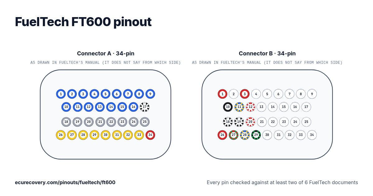
34 针 A 插头和 34 针 B 插头的每一个针脚,附 FuelTech 线束的线色。点击针脚即可查看它的功能。
每个针脚都至少与 6 份 FuelTech 资料中的两份核对在图上或表格中选择任一针脚,即可查看它的功能、线色以及核对时所用的资料。
FuelTech FT600 插头 A 针脚定义(34 针)
| 针脚 | 功能 | 线色 | FuelTech 说明 |
|---|---|---|---|
| A1 | Blue output #1 | Blue#1蓝色 | These outputs are usually used for injector control. When needed, they can be configured as auxiliary outputs. |
| A2 | Blue output #2 | Blue#2蓝色 | These outputs are usually used for injector control. When needed, they can be configured as auxiliary outputs. |
| A3 | Blue output #3 | Blue#3蓝色 | These outputs are usually used for injector control. When needed, they can be configured as auxiliary outputs. |
| A4 | Blue output #4 | Blue#4蓝色 | These outputs are usually used for injector control. When needed, they can be configured as auxiliary outputs. |
| A5 | Blue output #5 | Blue#5蓝色 | These outputs are usually used for injector control. When needed, they can be configured as auxiliary outputs. |
| A6 | Blue output #6 | Blue#6蓝色 | These outputs are usually used for injector control. When needed, they can be configured as auxiliary outputs. |
| A7 | Blue output #7 | Blue#7蓝色 | These outputs are usually used for injector control. When needed, they can be configured as auxiliary outputs. |
| A8 | Blue output #8 | Blue#8蓝色 | These outputs are usually used for injector control. When needed, they can be configured as auxiliary outputs. |
| A9 | Blue output #9 | Blue#9蓝色 | These outputs are usually used for injector control. When needed, they can be configured as auxiliary outputs. |
| A10 | Blue output #10 | Blue#10蓝色 | These outputs are usually used for injector control. When needed, they can be configured as auxiliary outputs. |
| A11 | Blue output #11 | Blue#11蓝色 | These outputs are usually used for injector control. When needed, they can be configured as auxiliary outputs. |
| A12 | Blue output #12 | Blue#12蓝色 | These outputs are usually used for injector control. When needed, they can be configured as auxiliary outputs. |
| A13 | Blue output #13 | Blue#13蓝色 | These outputs are usually used for injector control. When needed, they can be configured as auxiliary outputs. |
| A14 | Blue output #14 | Blue#14蓝色 | These outputs are usually used for injector control. When needed, they can be configured as auxiliary outputs. |
| A15 | Blue output #15 | Blue#15蓝色 | These outputs are usually used for injector control. When needed, they can be configured as auxiliary outputs. |
| A16 | Blue output #16 | Blue#16蓝色 | These outputs are usually used for injector control. When needed, they can be configured as auxiliary outputs. |
| A17 | Power ground input | Black/White黑色/白色 | Directly wired to the battery negative terminal with no seams. Do not tap any other grounds to this wire, it must run clean straight to the battery negative terminal. |
| A18 | Gray output#1 | Gray#1灰色 | These outputs are usually used for ignition control. When needed, they can be set up as injector outputs or auxiliary outputs. By standard, Gray output #8 is used as a tachometer output. |
| A19 | Gray output#2 | Gray#2灰色 | These outputs are usually used for ignition control. When needed, they can be set up as injector outputs or auxiliary outputs. By standard, Gray output #8 is used as a tachometer output. |
| A20 | Gray output#3 | Gray#3灰色 | These outputs are usually used for ignition control. When needed, they can be set up as injector outputs or auxiliary outputs. By standard, Gray output #8 is used as a tachometer output. |
| A21 | Gray output#4 | Gray#4灰色 | These outputs are usually used for ignition control. When needed, they can be set up as injector outputs or auxiliary outputs. By standard, Gray output #8 is used as a tachometer output. |
| A22 | Gray output#5 | Gray#5灰色 | These outputs are usually used for ignition control. When needed, they can be set up as injector outputs or auxiliary outputs. By standard, Gray output #8 is used as a tachometer output. |
| A23 | Gray output#6 | Gray#6灰色 | These outputs are usually used for ignition control. When needed, they can be set up as injector outputs or auxiliary outputs. By standard, Gray output #8 is used as a tachometer output. |
| A24 | Gray output#7 | Gray#7灰色 | These outputs are usually used for ignition control. When needed, they can be set up as injector outputs or auxiliary outputs. By standard, Gray output #8 is used as a tachometer output. |
| A25 | Gray output#8 | Gray#8灰色 | These outputs are usually used for ignition control. When needed, they can be set up as injector outputs or auxiliary outputs. By standard, Gray output #8 is used as a tachometer output. |
| A26 | Yellow output#1 | Yellow#1黄色 | Electronic throttle and step motor outputs. Also used as injection or auxiliary outputs (cooling fan, fuel pump, etc.) |
| A27 | Yellow output#2 | Yellow#2黄色 | Electronic throttle and step motor outputs. Also used as injection or auxiliary outputs (cooling fan, fuel pump, etc.) |
| A28 | Yellow output#3 | Yellow#3黄色 | Electronic throttle and step motor outputs. Also used as injection or auxiliary outputs (cooling fan, fuel pump, etc.) |
| A29 | Yellow output#4 | Yellow#4黄色 | Electronic throttle and step motor outputs. Also used as injection or auxiliary outputs (cooling fan, fuel pump, etc.) |
| A30 | Yellow output#5 | Yellow#5黄色 | Electronic throttle and step motor outputs. Also used as injection or auxiliary outputs (cooling fan, fuel pump, etc.) |
| A31 | Yellow output#6 | Yellow#6黄色 | Electronic throttle and step motor outputs. Also used as injection or auxiliary outputs (cooling fan, fuel pump, etc.) |
| A32 | Yellow output#7 | Yellow#7黄色 | Electronic throttle and step motor outputs. Also used as injection or auxiliary outputs (cooling fan, fuel pump, etc.) |
| A33 | Yellow output#8 | Yellow#8黄色 | Electronic throttle and step motor outputs. Also used as injection or auxiliary outputs (cooling fan, fuel pump, etc.) |
| A34 | 12V input from relay | Red红色 | Connected to the pin 87 of the Main Relay. |
FuelTech FT600 插头 B 针脚定义(34 针)
| 针脚 | 功能 | 线色 | FuelTech 说明 |
|---|---|---|---|
| B1 | RPM signal input | Red红色 | Connected to the crank trigger sensor (hall or magnetic) or to the distributor. To VR sensors, use the shield wire the sensor shield. To Hall sensor, do not use the shield as negative |
| B2 | Magnetic RPM sensor reference | White白色 | Connected to the negative wire of the magnetic sensor. When OEM ECU is reading the sensor in parallel, split this wire with OEM sensor negative - Do not connect when using hall effect sensor. |
| B3 | Cam sync signal input | Red红色 | Connected to the cam sync sensor (hall or magnetic) |
| B4 | Cam sync reference input | White白色 | Connected to the cam sync sensor (hall or magnetic) - Use the shield as negative to the sensor |
| B5 | White input#1 | White#1白色 | Default: O2 sensor input |
| B6 | White input#2 | White#2白色 | Default: two-step input |
| B7 | White input#3 | White#3白色 | Default: Air conditioning button |
| B8 | White input#4 | White#4白色 | Default: Oil pressure |
| B9 | White input#5 | White#5白色 | Default: Coolant temperature |
| B10 | Battery negative input | Black黑色 | Connected directly to the battery negative with no seams. Do not connect this wire to the chassis, engine block or head. |
| B11 | CAN A LOW | Yellow/Blue黄色/蓝色 | CAN A |
| B12 | CAN A HIGH | White/Red白色/红色 | CAN A |
| B13 | White input#6 | White#6白色 | Default: fuel pressure |
| B14 | White input#7 | White#7白色 | Default: Air temperature |
| B15 | White input#8 | White#8白色 | Default: pedal#2 signal input |
| B16 | White input#9 | White#9白色 | Default: pedal#1 signal input |
| B17 | White input#10 | White#10白色 | Default: MAP signal output, electronic throttle 1B input signal |
| B18 | Power ground inputs | Black/White黑色/白色 | Directly wired to the battery negative terminal with no seams. Do not tap any other grounds to this wire, it must run clean straight to the battery negative terminal. |
| B19 | Power ground inputs | Black/White黑色/白色 | Directly wired to the battery negative terminal with no seams. Do not tap any other grounds to this wire, it must run clean straight to the battery negative terminal. |
| B20 | CAN B HIGH | White/Red白色/红色 | |
| B21 | White input#11 | White#11白色 | Default: TPS sensor |
| B22 | White input#12 | White#12白色 | Sensors input |
| B23 | White input#13 | White#13白色 | Sensors input |
| B24 | White input#14 | White#14白色 | Sensors input |
| B25 | White input#15 | White#15白色 | Sensors input |
| B26 | 12V input from relay | Red红色 | Connected to the pin 87 of the Main Relay |
| B27 | 5V outputs for sensors | Green/Red绿色/红色 | 5V voltage output for TPS, electronic throttle and pedal sensors |
| B28 | CAN B LOW | Yellow/Blue黄色/蓝色 | |
| B29 | Ground for sensors | Green/Black绿色/黑色 | Connected the sensors ground |
| B30 | White input#16 | White#16白色 | Sensors input |
| B31 | White input#17 | White#17白色 | Sensors input |
| B32 | White input#18 | White#18白色 | Sensors input |
| B33 | White input#19 | White#19白色 | Power Shift Input - Blue wire Strain gage sensor (positive signal) |
| B34 | White input#20 | White#20白色 | Power Shift Input - Orange wire Strain gage sensor (negative signal) |
FuelTech 的 Map 文件被锁了? 免费检测。付款前你会先看到来自你自己文件的验证结果。
免费检测我的 MapFuelTech FT600 针脚速查
- FuelTech FT600 的 CAN 是哪几个针脚?
- CAN A LOW: 针脚 B11 (Yellow/Blue). CAN A HIGH: 针脚 B12 (White/Red). CAN B HIGH: 针脚 B20 (White/Red). CAN B LOW: 针脚 B28 (Yellow/Blue).
- FuelTech FT600 的曲轴和凸轮轴信号输入是哪几个针脚?
- RPM signal input: 针脚 B1 (Red). Magnetic RPM sensor reference: 针脚 B2 (White). Cam sync signal input: 针脚 B3 (Red). Cam sync reference input: 针脚 B4 (White).
- FuelTech FT600 的喷油嘴输出是哪几个针脚?
- Blue output #1: 针脚 A1 (Blue#1). Blue output #2: 针脚 A2 (Blue#2). Blue output #3: 针脚 A3 (Blue#3). Blue output #4: 针脚 A4 (Blue#4). Blue output #5: 针脚 A5 (Blue#5). Blue output #6: 针脚 A6 (Blue#6). Blue output #7: 针脚 A7 (Blue#7). Blue output #8: 针脚 A8 (Blue#8). Blue output #9: 针脚 A9 (Blue#9). Blue output #10: 针脚 A10 (Blue#10). Blue output #11: 针脚 A11 (Blue#11). Blue output #12: 针脚 A12 (Blue#12). Blue output #13: 针脚 A13 (Blue#13). Blue output #14: 针脚 A14 (Blue#14). Blue output #15: 针脚 A15 (Blue#15). Blue output #16: 针脚 A16 (Blue#16).
- FuelTech FT600 的点火输出是哪几个针脚?
- Gray output#1: 针脚 A18 (Gray#1). Gray output#2: 针脚 A19 (Gray#2). Gray output#3: 针脚 A20 (Gray#3). Gray output#4: 针脚 A21 (Gray#4). Gray output#5: 针脚 A22 (Gray#5). Gray output#6: 针脚 A23 (Gray#6). Gray output#7: 针脚 A24 (Gray#7). Gray output#8: 针脚 A25 (Gray#8).
- FuelTech FT600 的搭铁是哪几个针脚?
- Power ground input: 针脚 A17 (Black/White). Power ground inputs: 针脚 B18, B19 (Black/White).
- FuelTech FT600 的供电是哪几个针脚?
- 12V input from relay: 针脚 A34, B26 (Red).
- FuelTech FT600 的传感器供电是哪几个针脚?
- 5V outputs for sensors: 针脚 B27 (Green/Red).
资料来源
只使用 FuelTech 自己的资料。针脚名称和说明完全按照 FuelTech 的原文书写。
FuelTech FT450 / FT550 / FT550LITE / FT600 手册
FuelTech PRO600 线束手册(GEN-1)
FuelTech PRO600 线束手册(GEN-2)
FuelTech FT700 / FT700PLUS 完整手册(为 FT700 编写:针脚相同)
FuelTech FT700 快速参考(为 FT700 编写:针脚相同)
FuelTech PRO600 GEN III 线束手册
核对方法
- 我们从 FuelTech 这款 ECU 手册中的针脚表入手:针脚、线色和功能。
- 再在第二份 FuelTech 资料中把每个针脚重新读一遍:列出每个 ECU 针脚及其线色的线束手册,FT700 则使用其快速参考。由脚本逐针比对。
- 只有第二份资料给出相同的线色和功能,才会显示该针脚。FuelTech 的通用线以颜色加编号命名(Blue #1 即蓝色输出 1),所以编号也必须一致。
- 标签、说明和线色完全按照 FuelTech 的写法。
FuelTech 资料之间的不一致之处
B18:FuelTech 的 PRO600 线束手册(GEN-1、GEN-2 和 GEN III)把这根线列为 Black(黑色),接电池负极。FT600 手册以及 FT700 手册和快速参考则列为 Black/White(黑/白)电源搭铁。显示:Black/White,与 ECU 手册一致。
B19:FuelTech 的 PRO600 线束手册(GEN-1、GEN-2 和 GEN III)把这根线列为 Black(黑色),接电池负极。FT600 手册以及 FT700 手册和快速参考则列为 Black/White(黑/白)电源搭铁。显示:Black/White,与 ECU 手册一致。
ECU Recovery 与 FuelTech 无关联。FuelTech 及其产品名称是 FuelTech 的商标。如果你的线束附带了自己的接线图,请以它为准核对接线。
Map 被密码锁住了?
我们可以解锁 Haltech、MaxxECU、LinkECU、Vi-PEC、ECUMaster、Emtron 和 FuelTech 的 Map。你会先看到来自你自己文件的验证结果,确认有效才需支付 US$159.99。
解锁 Map