Pinagem da ECUMaster EMU PRO 8
ecurecovery.com/pinouts/ecumaster/emu-pro-8 · Cada pino conferido em 2 documentos da ECUMaster · dados conferidos em 2026-11-01
Pinagem da ECUMaster EMU PRO 8
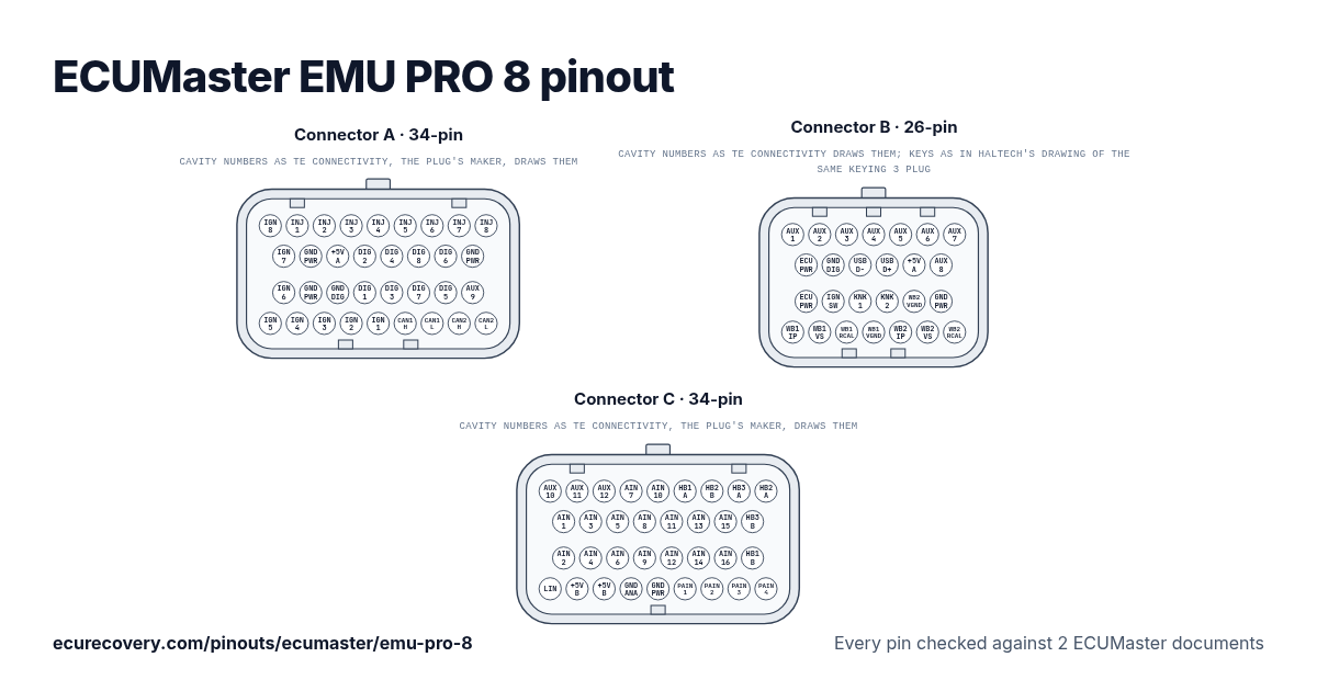
Cada pino dos conectores A (34 pinos), B (26 pinos) e C (34 pinos), com os nomes de pino da ECUMaster. Toque em um pino para ver o que ele faz.
Cada pino conferido em 2 documentos da ECUMasterEscolha qualquer pino no desenho ou na tabela para ver a função e os documentos em que foi conferido.
ECUMaster EMU PRO 8: pinagem do conector A (34 pinos)
Conector de acoplamento: TE AMP Superseal 1.0 4-1437290-1
| Pino | Função | Nota da ECUMaster |
|---|---|---|
| A1 | Ignition 8 | Output for active or passive ignition coils. |
| A2 | Injector 1 | Output for high or low impedance injectors. |
| A3 | Injector 2 | Output for high or low impedance injectors. |
| A4 | Injector 3 | Output for high or low impedance injectors. |
| A5 | Injector 4 | Output for high or low impedance injectors. |
| A6 | Injector 5 | Output for high or low impedance injectors. |
| A7 | Injector 6 | Output for high or low impedance injectors. |
| A8 | Injector 7 | Output for high or low impedance injectors. |
| A9 | Injector 8 | Output for high or low impedance injectors. |
| A10 | Ignition 7 | Output for active or passive ignition coils. |
| A11 | Power GND | Power ground. |
| A12 | +5V source A | +5V sensor supply, source A. |
| A13 | Digital 2 | Digital signal input. |
| A14 | Digital 4 | Digital signal input. |
| A15 | Digital 8 | Digital signal input. |
| A16 | Digital 6 (turbo) | Digital signal input, can be used for turboshaft speed sensor. |
| A17 | Power GND | Power ground. |
| A18 | Ignition 6 | Output for active or passive ignition coils. |
| A19 | Power GND | Power ground. |
| A20 | Digital GND | Digital ground. |
| A21 | Digital 1 (crank) | Digital signal input, dedicated crankshaft sensor input. |
| A22 | Digital 3 | Digital signal input. |
| A23 | Digital 7 | Digital signal input. |
| A24 | Digital 5 (turbo) | Digital signal input, can be used for turboshaft speed sensor. |
| A25 | Auxiliary 9 | Output for auxiliary devices. |
| A26 | Ignition 5 | Output for active or passive ignition coils. |
| A27 | Ignition 4 | Output for active or passive ignition coils. |
| A28 | Ignition 3 | Output for active or passive ignition coils. |
| A29 | Ignition 2 | Output for active or passive ignition coils. |
| A30 | Ignition 1 | Output for active or passive ignition coils. |
| A31 | CAN 1 high (PC comm) | CAN bus, fixed 1Mbps, used for communication with PC and peripheral devices. |
| A32 | CAN 1 low (PC comm) | CAN bus, fixed 1Mbps, used for communication with PC and peripheral devices. |
| A33 | CAN 2 high | CAN bus, configurable speed, used for communication with peripheral devices. |
| A34 | CAN 2 low | CAN bus, configurable speed, used for communication with peripheral devices. |
ECUMaster EMU PRO 8: pinagem do conector B (26 pinos)
Conector de acoplamento: TE AMP Superseal 1.0 1473416-1
| Pino | Função | Nota da ECUMaster |
|---|---|---|
| B1 | Auxiliary 1 (WBO heater) | Output for auxiliary devices, can be used as a WBO heater. |
| B2 | Auxiliary 2 (WBO heater) | Output for auxiliary devices, can be used as a WBO heater. |
| B3 | Auxiliary 3 (WBO heater) | Output for auxiliary devices, can be used as a WBO heater. |
| B4 | Auxiliary 4 (WBO heater) | Output for auxiliary devices, can be used as a WBO heater. |
| B5 | Auxiliary 5 | Output for auxiliary devices. |
| B6 | Auxiliary 6 | Output for auxiliary devices. |
| B7 | Auxiliary 7 | Output for auxiliary devices. |
| B8 | +12V supply | Power supply for the ECU and H-bridges. |
| B9 | Digital GND (flash drive) | Digital ground, recommended for flash drive connection. |
| B10 | USB D- (flash drive) | USB data pin for a flash drive, data logging. |
| B11 | USB D+ (flash drive) | USB data pin for a flash drive, data logging. |
| B12 | +5V source A (flash drive) | +5V sensor supply, source A, recommended for flash drive connection. |
| B13 | Auxiliary 8 | Output for auxiliary devices. |
| B14 | +12V supply | Power supply for the ECU and H-bridges. |
| B15 | +12V switched | +12V input to switch the ECU on or off. |
| B16 | Knock sensor 1 | Knock sensor input. |
| B17 | Knock sensor 2 | Knock sensor input. |
| B18 | WBO 2 VGND (LSU 4.9) | Wideband oxygen sensor input, LSU 4.9 Pin 2 (IPN / VM). |
| B19 | Power GND | Power ground. |
| B20 | WBO 1 IP (LSU 4.9) | Wideband oxygen sensor input, LSU 4.9 Pin 1 (APE / IP). |
| B21 | WBO 1 VS (LSU 4.9) | Wideband oxygen sensor input, LSU 4.9 Pin 6 (UN / RE). |
| B22 | WBO 1 RCAL (LSU 4.9) | Wideband oxygen sensor input, LSU 4.9 Pin 5 (RT / IA). |
| B23 | WBO 1 VGND (LSU 4.9) | Wideband oxygen sensor input, LSU 4.9 Pin 2 (IPN / VM). |
| B24 | WBO 2 IP (LSU 4.9) | Wideband oxygen sensor input, LSU 4.9 Pin 1 (APE / IP). |
| B25 | WBO 2 VS (LSU 4.9) | Wideband oxygen sensor input, LSU 4.9 Pin 6 (UN / RE). |
| B26 | WBO 2 RCAL (LSU 4.9) | Wideband oxygen sensor input, LSU 4.9 Pin 5 (RT / IA). |
ECUMaster EMU PRO 8: pinagem do conector C (34 pinos)
Conector de acoplamento: TE AMP Superseal 1.0 4-1437290-0
| Pino | Função | Nota da ECUMaster |
|---|---|---|
| C1 | Auxiliary 10 | Output for auxiliary devices. |
| C2 | Auxiliary 11 | Output for auxiliary devices. |
| C3 | Auxiliary 12 | Output for auxiliary devices. |
| C4 | Analog 7 | Analog signal input. |
| C5 | Analog 10 (2k2 pull) | Analog signal input. |
| C6 | H-bridge 1A | H-bridge output. |
| C7 | H-bridge 2B | H-bridge output. |
| C8 | H-bridge 3A | H-bridge output. |
| C9 | H-bridge 2A | H-bridge output. |
| C10 | Analog 1 (MAP) | Analog signal input, dedicated MAP sensor input. |
| C11 | Analog 3 | Analog signal input. |
| C12 | Analog 5 | Analog signal input. |
| C13 | Analog 8 | Analog signal input. |
| C14 | Analog 11 (2k2 pull) | Analog signal input. |
| C15 | Analog 13 (1k pull) | Analog signal input. |
| C16 | Analog 15 (330R pull) | Analog signal input. |
| C17 | H-bridge 3B | H-bridge output. |
| C18 | Analog 2 | Analog signal input. |
| C19 | Analog 4 | Analog signal input. |
| C20 | Analog 6 | Analog signal input. |
| C21 | Analog 9 (2k2 pull) | Analog signal input. |
| C22 | Analog 12 (2k2 pull) | Analog signal input. |
| C23 | Analog 14 (1k pull) | Analog signal input. |
| C24 | Analog 16 (100R pull) | Analog signal input. |
| C25 | H-bridge 1B | H-bridge output. |
| C26 | LIN | LIN network. |
| C27 | +5V source B | +5V sensor supply, source B. |
| C28 | +5V source B | +5V sensor supply, source B. |
| C29 | Analog GND | Analog ground. |
| C30 | Power GND | Power ground. |
| C31 | Precision analog 1 | High precision analog input. |
| C32 | Precision analog 2 | High precision analog input. |
| C33 | Precision analog 3 | High precision analog input. |
| C34 | Precision analog 4 | High precision analog input. |
Pinos da ECUMaster EMU PRO 8 em resumo
- Quais pinos são CAN na ECUMaster EMU PRO 8?
- CAN 1 high (PC comm): pino A31. CAN 1 low (PC comm): pino A32. CAN 2 high: pino A33. CAN 2 low: pino A34.
- Quais pinos são as saídas de injetores na ECUMaster EMU PRO 8?
- Injector 1: pino A2. Injector 2: pino A3. Injector 3: pino A4. Injector 4: pino A5. Injector 5: pino A6. Injector 6: pino A7. Injector 7: pino A8. Injector 8: pino A9.
- Quais pinos são as saídas de ignição na ECUMaster EMU PRO 8?
- Ignition 8: pino A1. Ignition 7: pino A10. Ignition 6: pino A18. Ignition 5: pino A26. Ignition 4: pino A27. Ignition 3: pino A28. Ignition 2: pino A29. Ignition 1: pino A30.
- Quais pinos são terra na ECUMaster EMU PRO 8?
- Power GND: pinos A11, A17, A19, B19, C30. Digital GND: pino A20. Digital GND (flash drive): pino B9. Analog GND: pino C29.
- Quais pinos alimentam a ECUMaster EMU PRO 8?
- +12V supply: pinos B8, B14. +12V switched: pino B15.
- Quais pinos alimentam os sensores na ECUMaster EMU PRO 8?
- +5V source A: pino A12. +5V source A (flash drive): pino B12. +5V source B: pinos C27, C28.
- Quais pinos são as ligações do sensor de banda larga na ECUMaster EMU PRO 8?
- WBO 2 VGND (LSU 4.9): pino B18. WBO 1 IP (LSU 4.9): pino B20. WBO 1 VS (LSU 4.9): pino B21. WBO 1 RCAL (LSU 4.9): pino B22. WBO 1 VGND (LSU 4.9): pino B23. WBO 2 IP (LSU 4.9): pino B24. WBO 2 VS (LSU 4.9): pino B25. WBO 2 RCAL (LSU 4.9): pino B26.
Folha de pinagem da ECUMaster EMU PRO 8
Uma folha para imprimir com cada pino, feita com os dados conferidos desta página.
De onde vem
Só documentos da própria ECUMaster. Os nomes dos pinos e as notas aparecem exatamente como a ECUMaster escreve, em inglês.
Pinagem da ECUMaster para esta ECU
Folha de pinagem compacta da ECUMaster (mini)
Desenho do conector: desenho de cliente da TE Connectivity (só para o desenho)Terceiro
Como conferimos
- Partimos do documento de pinagem da ECUMaster para esta ECU.
- Cada pino é lido de novo em um segundo documento da ECUMaster: a folha de pinagem compacta, o manual do usuário ou, para pinos iguais em uma ECU irmã, a pinagem dessa ECU. Quando nenhum segundo documento lista um pino, lemos uma segunda vez a olho na mesma pinagem.
- Um pino só aparece quando as duas leituras dão a mesma função. Os documentos da ECUMaster não indicam cores de fio, por isso nenhuma é mostrada.
- As notas são as descrições da própria ECUMaster na pinagem.
A ECU Recovery não tem vínculo com a ECUMaster. ECUMaster e os nomes dos seus produtos são marcas da ECUMaster. Se o seu chicote veio com um diagrama próprio, confira a sua ligação com ele.
Mapa bloqueado com senha?
Desbloqueamos mapas Haltech, MaxxECU, LinkECU, Vi-PEC, ECUMaster, Emtron e FuelTech. Primeiro você vê uma prova do seu próprio arquivo e só paga $159.99 se funcionar.
Desbloquear um mapa