Pinout de la MoTeC M600
ecurecovery.com/pinouts/motec/m600 · Cada pin comprobado en 2 documentos de MoTeC · datos comprobados el 2026-11-01
Pinout de la MoTeC M600
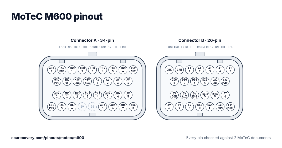
Cada pin del conector A de 34 pines y el B de 26 pines, con los nombres de pin de MoTeC. Toca un pin para ver qué hace.
Cada pin comprobado en 2 documentos de MoTeCElige cualquier pin del dibujo o de la tabla para ver su función y los documentos donde se comprobó.
MoTeC M600: pinout del conector A (34 pines)
| Pin | Función | Nota de MoTeC |
|---|---|---|
| A1 | Auxiliary Output 2 (AUX2) | |
| A2 | 5V Engine Sensor Supply (5V-ENG) | |
| A3 | Ignition Output 1 (IGN1) | Outputs marked * do not have a recirculation diode, see the Output Specifications for more detail. |
| A4 | Ignition Output 2 (IGN2) | Outputs marked * do not have a recirculation diode, see the Output Specifications for more detail. |
| A5 | Ignition Output 3 (IGN3) | Outputs marked * do not have a recirculation diode, see the Output Specifications for more detail. |
| A6 | Ignition Output 4 (IGN4) | Outputs marked * do not have a recirculation diode, see the Output Specifications for more detail. |
| A7 | Ignition Output 5 (Not available on M400) (IGN5) | Outputs marked * do not have a recirculation diode, see the Output Specifications for more detail. |
| A8 | Ignition Output 6 (Not available on M400) (IGN6) | Outputs marked * do not have a recirculation diode, see the Output Specifications for more detail. |
| A9 | 5V Auxiliary Sensor Supply (5V-AUX) | |
| A10 | Battery Negative (GND) | |
| A11 | Battery Negative (GND) | |
| A12 | 8V Engine Sensor Supply (8V-ENG) | |
| A13 | 8V Auxiliary Sensor and CAN Supply (8V-AUX) | |
| A14 | Analog Voltage Input 1 (AV1) | |
| A15 | Analog Voltage Input 2 (AV2) | |
| A16 | Analog Voltage Input 3 (AV3) | |
| A17 | Analog Voltage Input 4 (AV4) | |
| A18 | Auxiliary Output 1 (AUX1) | |
| A19 | Injector Output 1 (INJ1) | |
| A20 | Injector Output 2 (INJ2) | |
| A21 | Injector Output 3 (INJ3) | |
| A22 | Injector Output 4 (INJ4) | |
| A23 | Auxiliary Output 3 (AUX3) | Outputs marked * do not have a recirculation diode, see the Output Specifications for more detail. |
| A24 | Auxiliary Output 4 (AUX4) | Outputs marked * do not have a recirculation diode, see the Output Specifications for more detail. |
| A25 | Analog Voltage Input 5 (AV5) | |
| A26 | Battery Positive (VBAT) | |
| A27 | Injector Output 5 (Not available on M400) (INJ5) | |
| A28 | Injector Output 6 (Not available on M400) (INJ6) | |
| A29 | Sin uso | |
| A30 | Sin uso | |
| A31 | Auxiliary Output 5 (AUX5) | |
| A32 | Auxiliary Output 6 (AUX6) | |
| A33 | Auxiliary Output 7 (AUX7) | |
| A34 | Auxiliary Output 8 (AUX8) |
MoTeC M600: pinout del conector B (26 pines)
| Pin | Función | Nota de MoTeC |
|---|---|---|
| B1 | Crank Reference Timing Input (REF) | |
| B2 | Cam Sync Timing Input (SYNC) | |
| B3 | Analog Temperature Input 1 (AT1) | |
| B4 | Analog Temperature Input 2 (AT2) | |
| B5 | Analog Temperature Input 3 (AT3) | |
| B6 | Analog Temperature Input 4 (AT4) | |
| B7 | Analog Temperature Input 5 (AT5) | |
| B8 | Digital Input 1 (DIG1) | |
| B9 | Digital Input 2 (DIG2) | |
| B10 | Digital Input 3 (DIG3) | |
| B11 | Digital Input 4 (DIG4) | |
| B12 | Lambda2 Sense Voltage (Not available on M400) (LA2-S) | |
| B13 | Lambda2 Pump Current (Not available on M400) (LA2-P) | |
| B14 | 0V Comms (0V-COM) | |
| B15 | 0V Auxiliary Sensor Supply (0V-AUX) | |
| B16 | 0V Engine Sensor Supply (0V-ENG) | |
| B17 | RS232 Transmit Data (TX-232) | |
| B18 | RS232 Receive Data (RX-232) | |
| B19 | Analog Temperature Input 6 (AT6) | |
| B20 | Analog Voltage Input 6 (AV6) | |
| B21 | Analog Voltage Input 7 (AV7) | |
| B22 | Analog Voltage Input 8 (AV8) | |
| B23 | Can Bus High (CAN-HI) | |
| B24 | Can Bus Low (CAN-LO) | |
| B25 | Lambda1 Sense Voltage (LA1-S) | |
| B26 | Lambda1 Pump Current (LA1-P) |
Pines de la MoTeC M600 de un vistazo
- ¿Qué pines son CAN en la MoTeC M600?
- Can Bus High (CAN-HI): pin B23. Can Bus Low (CAN-LO): pin B24.
- ¿Qué pines son las entradas de cigüeñal y árbol de levas en la MoTeC M600?
- Crank Reference Timing Input (REF): pin B1. Cam Sync Timing Input (SYNC): pin B2.
- ¿Qué pines son las salidas de inyectores en la MoTeC M600?
- Injector Output 1 (INJ1): pin A19. Injector Output 2 (INJ2): pin A20. Injector Output 3 (INJ3): pin A21. Injector Output 4 (INJ4): pin A22. Injector Output 5 (Not available on M400) (INJ5): pin A27. Injector Output 6 (Not available on M400) (INJ6): pin A28.
- ¿Qué pines son las salidas de encendido en la MoTeC M600?
- Ignition Output 1 (IGN1): pin A3. Ignition Output 2 (IGN2): pin A4. Ignition Output 3 (IGN3): pin A5. Ignition Output 4 (IGN4): pin A6. Ignition Output 5 (Not available on M400) (IGN5): pin A7. Ignition Output 6 (Not available on M400) (IGN6): pin A8.
- ¿Qué pines son masa en la MoTeC M600?
- Battery Negative (GND): pines A10, A11. 0V Comms (0V-COM): pin B14. 0V Auxiliary Sensor Supply (0V-AUX): pin B15. 0V Engine Sensor Supply (0V-ENG): pin B16.
- ¿Qué pines alimentan la MoTeC M600?
- Battery Positive (VBAT): pin A26.
- ¿Qué pines alimentan los sensores en la MoTeC M600?
- 5V Engine Sensor Supply (5V-ENG): pin A2. 5V Auxiliary Sensor Supply (5V-AUX): pin A9. 8V Engine Sensor Supply (8V-ENG): pin A12. 8V Auxiliary Sensor and CAN Supply (8V-AUX): pin A13.
- ¿Qué pines son las conexiones del sensor de banda ancha en la MoTeC M600?
- Lambda2 Sense Voltage (Not available on M400) (LA2-S): pin B12. Lambda2 Pump Current (Not available on M400) (LA2-P): pin B13. Lambda1 Sense Voltage (LA1-S): pin B25. Lambda1 Pump Current (LA1-P): pin B26.
Hoja de pinout de la MoTeC M600
Una hoja imprimible con cada pin, hecha con los datos comprobados de esta página.
De dónde sale
Solo documentos del propio MoTeC. Los nombres de los pines y las notas se muestran tal como los escribe MoTeC, en inglés.
Manual de usuario de MoTeC (lista de pines por función)
Diagrama de cableado de MoTeC
Cómo lo comprobamos
- Partimos de la lista de pines del manual de usuario de MoTeC para esta ECU (Apéndice L: lista de pines por función).
- Leemos cada pin otra vez en un segundo documento de MoTeC: el diagrama de cableado de la ECU (para la M84, su hoja de datos). Un script los compara pin por pin; cuando la etiqueta de un diagrama queda entre dos pines, la leemos a ojo.
- Un pin solo se muestra cuando ambos documentos indican la misma función. Los pines que el manual marca como no disponibles en este modelo se muestran sin uso. MoTeC no define colores de cable estándar, así que no se muestran.
- Las notas son las propias palabras de MoTeC en el manual.
ECU Recovery no está afiliada a MoTeC. MoTeC y sus nombres de producto son marcas de MoTeC. Si tu arnés trae su propio diagrama, compara tu cableado con él.
¿Mapa bloqueado con contraseña?
Desbloqueamos mapas de Haltech, MaxxECU, LinkECU, Vi-PEC, ECUMaster, Emtron y FuelTech. Primero ves una prueba de tu propio archivo y solo pagas $159.99 si funciona.
Desbloquear un mapa