Pinout de la MoTeC M190
ecurecovery.com/pinouts/motec/m190 · Cada pin comprobado en 3 documentos de MoTeC · datos comprobados el 2026-11-01
Pinout de la MoTeC M190
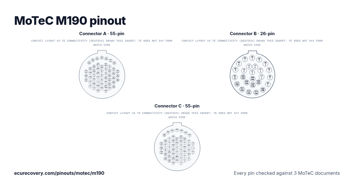
Cada pin de los conectores A (55 pines), B (26 pines) y C (55 pines), con los nombres de pin de MoTeC. Toca un pin para ver qué hace.
Cada pin comprobado en 3 documentos de MoTeCElige cualquier pin del dibujo o de la tabla para ver su función y los documentos donde se comprobó.
MoTeC M190: pinout del conector A (55 pines)
Conector de acople: Autosport 55 way Yellow - (Deutsch) AS6-16-35SA – MoTeC #65031
| Pin | Función | Nota de MoTeC |
|---|---|---|
| A01 | Low Side Injector 3 (INJ_LS3) | |
| A02 | Low Side Injector 2 (INJ_LS2) | |
| A03 | Low Side Injector 1 (INJ_LS1) | |
| A04 | Low Side Injector 12 (INJ_LS12) | |
| A05 | Low Side Injector 4 (INJ_LS4) | |
| A06 | Lambda Narrow Input 2 (LA_NB2) | |
| A07 | Lambda Narrow Input 1 (LA_NB1) | |
| A08 | Sensor 5.0V C (SEN_5V0_C1) | |
| A09 | Sensor 5.0V C (SEN_5V0_C2) | |
| A10 | Low Side Injector 8 (INJ_LS8) | |
| A11 | Peak Hold Injector 1 (INJ_PH1) | |
| A12 | Peak Hold Injector 2 (INJ_PH2) | |
| A13 | Analogue Voltage Input 11 (AV11) | |
| A14 | Digital Input 2 (DIG2) | |
| A15 | RS232 Receive (RS232_RX) | |
| A16 | Sensor 5.0V C (SEN_5V0_C3) | |
| A17 | Low Side Injector 11 (INJ_LS11) | |
| A18 | Sensor 0V C (SEN_0V_C1) | |
| A19 | Sensor 0V C (SEN_0V_C2) | |
| A20 | Sensor 0V C (SEN_0V_C3) | |
| A21 | Digital Input 1 (DIG1) | |
| A22 | LIN Bus (LIN) | |
| A23 | RS232 Transmit (RS232_TX) | |
| A24 | CAN Bus 2 High (CAN2_HI) | |
| A25 | Low Side Injector 7 (INJ_LS7) | |
| A26 | Peak Hold Injector 3 (INJ_PH3) | |
| A27 | Analogue Voltage Input 15 (AV15) | |
| A28 | Analogue Voltage Input 16 (AV16) | |
| A29 | Analogue Voltage Input 17 (AV17) | |
| A30 | Digital Input 3 (DIG3) | |
| A31 | CAN Bus 2 Low (CAN2_LO) | |
| A32 | Low Side Injector 10 (INJ_LS10) | |
| A33 | Peak Hold Injector 4 (INJ_PH4) | |
| A34 | Analogue Voltage Input 13 (AV13) | |
| A35 | Analogue Voltage Input 12 (AV12) | |
| A36 | Peak Hold Injector 7 (INJ_PH7) | |
| A37 | Digital Input 4 (DIG4) | |
| A38 | Battery Backup (BAT_BAK) | |
| A39 | CAN Bus 3 High (CAN3_HI) | |
| A40 | Low Side Injector 6 (INJ_LS6) | |
| A41 | Analogue Voltage Input 14 (AV14) | |
| A42 | Peak Hold Injector 9 (INJ_PH9) | |
| A43 | Peak Hold Injector 10 (INJ_PH10) | |
| A44 | Peak Hold Injector 6 (INJ_PH6) | |
| A45 | Peak Hold Injector 5 (INJ_PH5) | |
| A46 | CAN Bus 3 Low (CAN3_LO) | |
| A47 | Low Side Injector 9 (INJ_LS9) | |
| A48 | Low Side Injector 5 (INJ_LS5) | |
| A49 | Peak Hold Injector 11 (INJ_PH11) | |
| A50 | Peak Hold Injector 12 (INJ_PH12) | |
| A51 | Peak Hold Injector 8 (INJ_PH8) | |
| A52 | Low Side Ignition 12 (IGN_LS12) | |
| A53 | Low Side Ignition 9 (IGN_LS9) | |
| A54 | Low Side Ignition 10 (IGN_LS10) | |
| A55 | Low Side Ignition 11 (IGN_LS11) |
MoTeC M190: pinout del conector B (26 pines)
Conector de acople: Autosport 26 way Red - (Deutsch) AS6-16-26SN – MoTeC #65034
| Pin | Función | Nota de MoTeC |
|---|---|---|
| B_A | Half Bridge Output 1 (OUT_HB1) | |
| B_B | Half Bridge Output 2 (OUT_HB2) | |
| B_C | Half Bridge Output 3 (OUT_HB3) | |
| B_D | Half Bridge Output 4 (OUT_HB4) | |
| B_E | Half Bridge Output 5 (OUT_HB5) | |
| B_F | Half Bridge Output 6 (OUT_HB6) | |
| B_G | Battery Negative (BAT_NEG1) | |
| B_H | Battery Positive (BAT_POS1) | |
| B_J | Battery Positive (BAT_POS2) | |
| B_K | Battery Positive (BAT_POS3) | |
| B_L | Battery Positive (BAT_POS4) | |
| B_M | Half Bridge Output 10 (OUT_HB10) | |
| B_N | Half Bridge Output 9 (OUT_HB9) | |
| B_P | Half Bridge Output 8 (OUT_HB8) | |
| B_R | Half Bridge Output 7 (OUT_HB7) | |
| B_S | Low Side Output 4 (OUT_LS4) | |
| B_T | Low Side Output 6 (OUT_LS6) | |
| B_U | Low Side Output 1 (OUT_LS1) | |
| B_V | Low Side Output 2 (OUT_LS2) | |
| B_W | Battery Negative (BAT_NEG2) | |
| B_X | Battery Negative (BAT_NEG3) | |
| B_Y | Battery Negative (BAT_NEG4) | |
| B_Z | Battery Negative (BAT_NEG5) | |
| B_a | Low Side Output 5 (OUT_LS5) | |
| B_b | Low Side Output 3 (OUT_LS3) | |
| B_c | Battery Negative (BAT_NEG6) |
MoTeC M190: pinout del conector C (55 pines)
Conector de acople: Autosport 55 way Red - (Deutsch) AS6-16-35SN – MoTeC #68090
| Pin | Función | Nota de MoTeC |
|---|---|---|
| C01 | Low Side Ignition 4 (IGN_LS4) | |
| C02 | Low Side Ignition 3 (IGN_LS3) | |
| C03 | Low Side Ignition 8 (IGN_LS8) | |
| C04 | Low Side Ignition 6 (IGN_LS6) | |
| C05 | Low Side Ignition 5 (IGN_LS5) | |
| C06 | Analogue Voltage Input 8 (AV8) | |
| C07 | Analogue Voltage Input 10 (AV10) | |
| C08 | Low Side Ignition 2 (IGN_LS2) | |
| C09 | Low Side Ignition 7 (IGN_LS7) | |
| C10 | Universal Digital Input 8 (UDIG8) | |
| C11 | Analogue Voltage Input 6 (AV6) | |
| C12 | Analogue Voltage Input 7 (AV7) | |
| C13 | Analogue Voltage Input 9 (AV9) | |
| C14 | Sensor 0V A (SEN_0V_A1) | |
| C15 | Sensor 0V A (SEN_0V_A2) | |
| C16 | Low Side Ignition 1 (IGN_LS1) | |
| C17 | Universal Digital Input 7 (UDIG7) | |
| C18 | Universal Digital Input 1 (UDIG1) | |
| C19 | Universal Digital Input 12 (UDIG12) | |
| C20 | Universal Digital Input 11 (UDIG11) | |
| C21 | Universal Digital Input 10 (UDIG10) | |
| C22 | Universal Digital Input 9 (UDIG9) | |
| C23 | Sensor 0V B (SEN_0V_B1) | |
| C24 | CAN Bus 1 High (CAN1_HI) | |
| C25 | Universal Digital Input 3 (UDIG3) | |
| C26 | Ethernet Receive- (ETH_RX-) | Ethernet Orange |
| C27 | Universal Digital Input 4 (UDIG4) | |
| C28 | Analogue Voltage Input 4 (AV4) | |
| C29 | Analogue Voltage Input 5 (AV5) | |
| C30 | Sensor 0V B (SEN_0V_B2) | |
| C31 | CAN Bus 1 Low (CAN1_LO) | |
| C32 | Universal Digital Input 2 (UDIG2) | |
| C33 | Ethernet Receive+ (ETH_RX+) | Ethernet |
| C34 | Ethernet Transmit- (ETH_TX-) | Ethernet Green |
| C35 | Analogue Voltage Input 3 (AV3) | |
| C36 | Analogue Voltage Input 2 (AV2) | |
| C37 | Analogue Temperature Input 1 (AT1) | 1k Pull up to SEN_5V_A |
| C38 | Analogue Temperature Input 3 (AT3) | 1k Pull up to SEN_5V_B |
| C39 | Analogue Temperature Input 2 (AT2) | 1k Pull up to SEN_5V_A |
| C40 | Universal Digital Input 5 (UDIG5) | |
| C41 | Ethernet Transmit+ (ETH_TX+) | Ethernet |
| C42 | Analogue Voltage Input 1 (AV1) | |
| C43 | Knock Input 3 (KNOCK3) | |
| C44 | Knock Input 2 (KNOCK2) | |
| C45 | Analogue Temperature Input 5 (AT5) | 1k Pull up to SEN_5V_C |
| C46 | Analogue Temperature Input 4 (AT4) | 1k Pull up to SEN_5V_B |
| C47 | Universal Digital Input 6 (UDIG6) | |
| C48 | Sensor 5.0V A (SEN_5V0_A1) | |
| C49 | Knock Input 4 (KNOCK4) | |
| C50 | Sensor 5.0V B (SEN_5V0_B1) | |
| C51 | Knock Input 1 (KNOCK1) | |
| C52 | Analogue Temperature Input 6 (AT6) | 1k Pull up to SEN_5V_C |
| C53 | Sensor 5.0V A (SEN_5V0_A2) | |
| C54 | Sensor 6.3V (SEN_6V3) | |
| C55 | Sensor 5.0V B (SEN_5V0_B2) |
Pines de la MoTeC M190 de un vistazo
- ¿Qué pines son CAN en la MoTeC M190?
- CAN Bus 2 High (CAN2_HI): pin A24. CAN Bus 2 Low (CAN2_LO): pin A31. CAN Bus 3 High (CAN3_HI): pin A39. CAN Bus 3 Low (CAN3_LO): pin A46. CAN Bus 1 High (CAN1_HI): pin C24. CAN Bus 1 Low (CAN1_LO): pin C31.
- ¿Qué pines son las salidas de inyectores en la MoTeC M190?
- Low Side Injector 3 (INJ_LS3): pin A01. Low Side Injector 2 (INJ_LS2): pin A02. Low Side Injector 1 (INJ_LS1): pin A03. Low Side Injector 12 (INJ_LS12): pin A04. Low Side Injector 4 (INJ_LS4): pin A05. Low Side Injector 8 (INJ_LS8): pin A10. Peak Hold Injector 1 (INJ_PH1): pin A11. Peak Hold Injector 2 (INJ_PH2): pin A12. Low Side Injector 11 (INJ_LS11): pin A17. Low Side Injector 7 (INJ_LS7): pin A25. Peak Hold Injector 3 (INJ_PH3): pin A26. Low Side Injector 10 (INJ_LS10): pin A32. Peak Hold Injector 4 (INJ_PH4): pin A33. Peak Hold Injector 7 (INJ_PH7): pin A36. Low Side Injector 6 (INJ_LS6): pin A40. Peak Hold Injector 9 (INJ_PH9): pin A42. Peak Hold Injector 10 (INJ_PH10): pin A43. Peak Hold Injector 6 (INJ_PH6): pin A44. Peak Hold Injector 5 (INJ_PH5): pin A45. Low Side Injector 9 (INJ_LS9): pin A47. Low Side Injector 5 (INJ_LS5): pin A48. Peak Hold Injector 11 (INJ_PH11): pin A49. Peak Hold Injector 12 (INJ_PH12): pin A50. Peak Hold Injector 8 (INJ_PH8): pin A51.
- ¿Qué pines son las salidas de encendido en la MoTeC M190?
- Low Side Ignition 12 (IGN_LS12): pin A52. Low Side Ignition 9 (IGN_LS9): pin A53. Low Side Ignition 10 (IGN_LS10): pin A54. Low Side Ignition 11 (IGN_LS11): pin A55. Low Side Ignition 4 (IGN_LS4): pin C01. Low Side Ignition 3 (IGN_LS3): pin C02. Low Side Ignition 8 (IGN_LS8): pin C03. Low Side Ignition 6 (IGN_LS6): pin C04. Low Side Ignition 5 (IGN_LS5): pin C05. Low Side Ignition 2 (IGN_LS2): pin C08. Low Side Ignition 7 (IGN_LS7): pin C09. Low Side Ignition 1 (IGN_LS1): pin C16.
- ¿Qué pines son masa en la MoTeC M190?
- Sensor 0V C (SEN_0V_C1): pin A18. Sensor 0V C (SEN_0V_C2): pin A19. Sensor 0V C (SEN_0V_C3): pin A20. Battery Negative (BAT_NEG1): pin B_G. Battery Negative (BAT_NEG2): pin B_W. Battery Negative (BAT_NEG3): pin B_X. Battery Negative (BAT_NEG4): pin B_Y. Battery Negative (BAT_NEG5): pin B_Z. Battery Negative (BAT_NEG6): pin B_c. Sensor 0V A (SEN_0V_A1): pin C14. Sensor 0V A (SEN_0V_A2): pin C15. Sensor 0V B (SEN_0V_B1): pin C23. Sensor 0V B (SEN_0V_B2): pin C30.
- ¿Qué pines alimentan la MoTeC M190?
- Battery Positive (BAT_POS1): pin B_H. Battery Positive (BAT_POS2): pin B_J. Battery Positive (BAT_POS3): pin B_K. Battery Positive (BAT_POS4): pin B_L.
- ¿Qué pines alimentan los sensores en la MoTeC M190?
- Sensor 5.0V C (SEN_5V0_C1): pin A08. Sensor 5.0V C (SEN_5V0_C2): pin A09. Sensor 5.0V C (SEN_5V0_C3): pin A16. Sensor 5.0V A (SEN_5V0_A1): pin C48. Sensor 5.0V B (SEN_5V0_B1): pin C50. Sensor 5.0V A (SEN_5V0_A2): pin C53. Sensor 5.0V B (SEN_5V0_B2): pin C55.
Hoja de pinout de la MoTeC M190
Una hoja imprimible con cada pin, hecha con los datos comprobados de esta página.
De dónde sale
Solo documentos del propio MoTeC. Los nombres de los pines y las notas se muestran tal como los escribe MoTeC, en inglés.
Hoja de datos de MoTeC
Página del producto de MoTeC (tablas de pines)
Manual de hardware de MoTeC
Dibujo del conector: catálogo Deutsch Autosport de TE Connectivity, disposiciones de inserto (solo para el dibujo)Tercero
Cómo lo comprobamos
- Partimos de la hoja de datos de MoTeC para esta ECU.
- Volvemos a leer cada pin en la página del producto de MoTeC y, cuando cubre esta ECU, en su manual de hardware. Un script los compara, pin por pin.
- Un pin solo se muestra cuando su nombre y su nombre completo coinciden en todos los documentos. MoTeC no fija colores de cable estándar, así que no se muestran.
- Las notas son palabras del propio MoTeC, mostradas cuando dos de sus documentos las imprimen igual.
Donde los documentos de MoTeC no coinciden
B_S: el manual M1 ECU Hardware de MoTeC de 2013 llama a este pin Low Side Injector 4 (INJ_LS4), un nombre que el mismo manual también da al pin A05. La hoja de datos del M190 de MoTeC (julio de 2020) y su página actual del M190 indican Low Side Output 4 (OUT_LS4), y eso es lo que mostramos.
B_T: el manual M1 ECU Hardware de MoTeC de 2013 llama a este pin Low Side Injector 6 (INJ_LS6), un nombre que el mismo manual también da al pin A40. La hoja de datos del M190 de MoTeC (julio de 2020) y su página actual del M190 indican Low Side Output 6 (OUT_LS6), y eso es lo que mostramos.
B_U: el manual M1 ECU Hardware de MoTeC de 2013 llama a este pin Low Side Injector 1 (INJ_LS1), un nombre que el mismo manual también da al pin A03. La hoja de datos del M190 de MoTeC (julio de 2020) y su página actual del M190 indican Low Side Output 1 (OUT_LS1), y eso es lo que mostramos.
B_V: el manual M1 ECU Hardware de MoTeC de 2013 llama a este pin Low Side Injector 2 (INJ_LS2), un nombre que el mismo manual también da al pin A02. La hoja de datos del M190 de MoTeC (julio de 2020) y su página actual del M190 indican Low Side Output 2 (OUT_LS2), y eso es lo que mostramos.
B_a: el manual M1 ECU Hardware de MoTeC de 2013 llama a este pin Low Side Injector 5 (INJ_LS5), un nombre que el mismo manual también da al pin A48. La hoja de datos del M190 de MoTeC (julio de 2020) y su página actual del M190 indican Low Side Output 5 (OUT_LS5), y eso es lo que mostramos.
B_b: el manual M1 ECU Hardware de MoTeC de 2013 llama a este pin Low Side Injector 3 (INJ_LS3), un nombre que el mismo manual también da al pin A01. La hoja de datos del M190 de MoTeC (julio de 2020) y su página actual del M190 indican Low Side Output 3 (OUT_LS3), y eso es lo que mostramos.
ECU Recovery no está afiliada a MoTeC. MoTeC y sus nombres de producto son marcas de MoTeC. Si tu arnés trae su propio diagrama, compara tu cableado con él.
¿Mapa bloqueado con contraseña?
Desbloqueamos mapas de Haltech, MaxxECU, LinkECU, Vi-PEC, ECUMaster, Emtron y FuelTech. Primero ves una prueba de tu propio archivo y solo pagas $159.99 si funciona.
Desbloquear un mapa