Pinout de la FuelTech FT700
ecurecovery.com/pinouts/fueltech/ft700 · Cada pin comprobado en 2 documentos de FuelTech · datos comprobados el 2026-11-04
Pinout de la FuelTech FT700
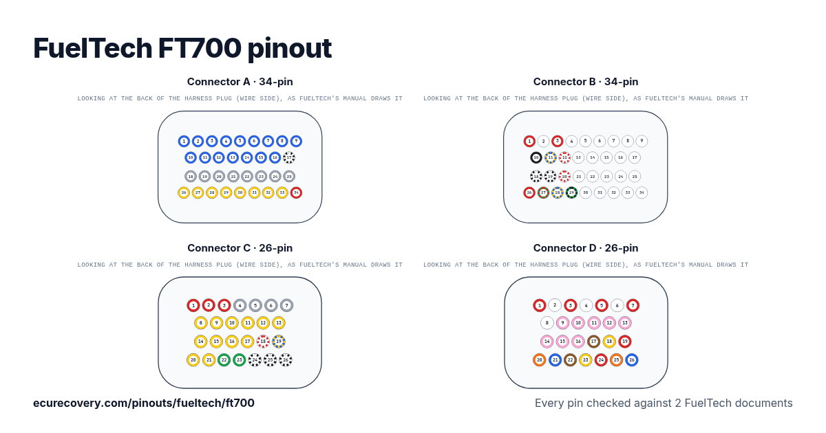
Cada pin de los conectores A (34 pines), B (34 pines), C (26 pines) y D (26 pines), con los colores de cable del arnés de FuelTech. Toca un pin para ver qué hace.
Cada pin comprobado en 2 documentos de FuelTechElige cualquier pin del dibujo o de la tabla para ver su función, el color de su cable y los documentos donde se comprobó.
FuelTech FT700: pinout del conector A (34 pines)
| Pin | Función | Cable | Nota de FuelTech |
|---|---|---|---|
| A1 | Blue output #01 | Blue#01Azul | These outputs are usually used for injector control. When needed, they can be configured as auxiliary outputs. |
| A2 | Blue output #02 | Blue#02Azul | These outputs are usually used for injector control. When needed, they can be configured as auxiliary outputs. |
| A3 | Blue output #03 | Blue#03Azul | These outputs are usually used for injector control. When needed, they can be configured as auxiliary outputs. |
| A4 | Blue output #04 | Blue#04Azul | These outputs are usually used for injector control. When needed, they can be configured as auxiliary outputs. |
| A5 | Blue output #05 | Blue#05Azul | These outputs are usually used for injector control. When needed, they can be configured as auxiliary outputs. |
| A6 | Blue output #06 | Blue#06Azul | These outputs are usually used for injector control. When needed, they can be configured as auxiliary outputs. |
| A7 | Blue output #07 | Blue#07Azul | These outputs are usually used for injector control. When needed, they can be configured as auxiliary outputs. |
| A8 | Blue output #08 | Blue#08Azul | These outputs are usually used for injector control. When needed, they can be configured as auxiliary outputs. |
| A9 | Blue output #09 | Blue#09Azul | These outputs are usually used for injector control. When needed, they can be configured as auxiliary outputs. |
| A10 | Blue output #10 | Blue#10Azul | These outputs are usually used for injector control. When needed, they can be configured as auxiliary outputs. |
| A11 | Blue output #11 | Blue#11Azul | These outputs are usually used for injector control. When needed, they can be configured as auxiliary outputs. |
| A12 | Blue output #12 | Blue#12Azul | These outputs are usually used for injector control. When needed, they can be configured as auxiliary outputs. |
| A13 | Blue output #13 | Blue#13Azul | These outputs are usually used for injector control. When needed, they can be configured as auxiliary outputs. |
| A14 | Blue output #14 | Blue#14Azul | These outputs are usually used for injector control. When needed, they can be configured as auxiliary outputs. |
| A15 | Blue output #15 | Blue#15Azul | These outputs are usually used for injector control. When needed, they can be configured as auxiliary outputs. |
| A16 | Blue output #16 | Blue#16Azul | These outputs are usually used for injector control. When needed, they can be configured as auxiliary outputs. |
| A17 | Power ground | Black/WhiteNegro/blanco | Directly wired to the battery negative terminal with no seams. Do not tap any other grounds to this wire, it must run clean straight to the battery negative terminal. |
| A18 | Gray output#01 | Gray#01Gris | These outputs are usually used for ignition control. When needed, they can be set up as injector outputs (Peak and Hold driver required) By standard, Gray output #08 is used as a tachometer output. |
| A19 | Gray output#02 | Gray#02Gris | These outputs are usually used for ignition control. When needed, they can be set up as injector outputs (Peak and Hold driver required) By standard, Gray output #08 is used as a tachometer output. |
| A20 | Gray output#03 | Gray#03Gris | These outputs are usually used for ignition control. When needed, they can be set up as injector outputs (Peak and Hold driver required) By standard, Gray output #08 is used as a tachometer output. |
| A21 | Gray output#04 | Gray#04Gris | These outputs are usually used for ignition control. When needed, they can be set up as injector outputs (Peak and Hold driver required) By standard, Gray output #08 is used as a tachometer output. |
| A22 | Gray output#05 | Gray#05Gris | These outputs are usually used for ignition control. When needed, they can be set up as injector outputs (Peak and Hold driver required) By standard, Gray output #08 is used as a tachometer output. |
| A23 | Gray output#06 | Gray#06Gris | These outputs are usually used for ignition control. When needed, they can be set up as injector outputs (Peak and Hold driver required) By standard, Gray output #08 is used as a tachometer output. |
| A24 | Gray output#07 | Gray#07Gris | These outputs are usually used for ignition control. When needed, they can be set up as injector outputs (Peak and Hold driver required) By standard, Gray output #08 is used as a tachometer output. |
| A25 | Gray output#08 | Gray#08Gris | These outputs are usually used for ignition control. When needed, they can be set up as injector outputs (Peak and Hold driver required) By standard, Gray output #08 is used as a tachometer output. |
| A26 | Yellow output#01 | Yellow#01Amarillo | Electronic throttle and step motor outputs. Also used as injection or auxiliary outputs (cooling fan, fuel pump, etc.) |
| A27 | Yellow output#02 | Yellow#02Amarillo | Electronic throttle and step motor outputs. Also used as injection or auxiliary outputs (cooling fan, fuel pump, etc.) |
| A28 | Yellow output#03 | Yellow#03Amarillo | Electronic throttle and step motor outputs. Also used as injection or auxiliary outputs (cooling fan, fuel pump, etc.) |
| A29 | Yellow output#04 | Yellow#04Amarillo | Electronic throttle and step motor outputs. Also used as injection or auxiliary outputs (cooling fan, fuel pump, etc.) |
| A30 | Yellow output#05 | Yellow#05Amarillo | Electronic throttle and step motor outputs. Also used as injection or auxiliary outputs (cooling fan, fuel pump, etc.) |
| A31 | Yellow output#06 | Yellow#06Amarillo | Electronic throttle and step motor outputs. Also used as injection or auxiliary outputs (cooling fan, fuel pump, etc.) |
| A32 | Yellow output#07 | Yellow#07Amarillo | Electronic throttle and step motor outputs. Also used as injection or auxiliary outputs (cooling fan, fuel pump, etc.) |
| A33 | Yellow output#08 | Yellow#08Amarillo | Electronic throttle and step motor outputs. Also used as injection or auxiliary outputs (cooling fan, fuel pump, etc.) |
| A34 | 12V input from relay | RedRojo | Connected to the pin 87 of the Main Relay. |
FuelTech FT700: pinout del conector B (34 pines)
| Pin | Función | Cable | Nota de FuelTech |
|---|---|---|---|
| B1 | RPM signal input | RedRojo | Connected to the crank trigger sensor (hall or magnetic) or to the distributor. |
| B2 | Magnetic RPM sensor reference | WhiteBlanco | Connected to the negative wire of the magnetic sensor, split the wire with OEM reference sensor - Do not connect when using hall effect sensor. |
| B3 | Cam sync signal input | RedRojo | Connected to the cam sync sensor (hall or magnetic) |
| B4 | Cam sync reference input | WhiteBlanco | Connected to the negative wire of the magnetic sensor. When OEM ECU is reading the sensor in parallel, split this wire with OEM sensor negative - Do not use the shield as negative to the sensor |
| B5 | White input#01 * | White#01Blanco | Default: O2 sensor input |
| B6 | White input#02 * | White#02Blanco | Default: two-step input |
| B7 | White input#03 * | White#03Blanco | Default: Air conditioning button |
| B8 | White input#04 * | White#04Blanco | Default: Oil pressure |
| B9 | White input#05 * | White#05Blanco | Default: Coolant temperature |
| B10 | Battery negative | BlackNegro | Connected directly to the battery negative with no seams. Do not connect this wire to the chassis, engine block or head. |
| B11 | CAN A LOW | Yellow/BlueAmarillo/azul | CAN A |
| B12 | CAN A HIGH | White/RedBlanco/rojo | CAN A |
| B13 | White input#06 * | White#06Blanco | Default: fuel pressure |
| B14 | White input#07 * | White#07Blanco | Default: Air temperature |
| B15 | White input#08 * | White#08Blanco | Default: pedal#2 signal input |
| B16 | White input#09 * | White#09Blanco | Default: pedal#1 signal input |
| B17 | White input#10 * | White#10Blanco | Default: MAP signal output, electronic throttle 1B input signal |
| B18 | Power ground | Black/WhiteNegro/blanco | Directly wired to the battery negative terminal with no seams. Do not tap any other grounds to this wire, it must run clean straight to the battery negative terminal. |
| B19 | Power ground | Black/WhiteNegro/blanco | Directly wired to the battery negative terminal with no seams. Do not tap any other grounds to this wire, it must run clean straight to the battery negative terminal. |
| B20 | CAN B HIGH | White/RedBlanco/rojo | |
| B21 | White input#11 * | White#11Blanco | Default: TPS sensor |
| B22 | White input#12 | White#12Blanco | Generic sensor input |
| B23 | White input#13 | White#13Blanco | Generic sensor input |
| B24 | White input#14 | White#14Blanco | Generic sensor input |
| B25 | White input#15 | White#15Blanco | Generic sensor input |
| B26 | 12V input from relay | RedRojo | Connected to the pin 87 of the Main Relay |
| B27 | 5V outputs for sensors | Green/RedVerde/rojo | 5V voltage output for TPS, electronic throttle and pedal sensors |
| B28 | CAN B LOW | Yellow/BlueAmarillo/azul | |
| B29 | Ground for sensors | Green/BlackVerde/negro | Connected the sensors ground |
| B30 | White input#16 | White#16Blanco | Generic sensor input |
| B31 | White input#17 | White#17Blanco | Generic sensor input |
| B32 | White input#18 | White#18Blanco | Generic sensor input |
| B33 | White input#19 | White#19Blanco | Strain gauge input - Blue wire Strain gage sensor (positive signal) |
| B34 | White input#20 | White#20Blanco | Strain gauge input - Orange wire Strain gage sensor (negative signal) |
FuelTech FT700: pinout del conector C (26 pines)
| Pin | Función | Cable | Nota de FuelTech |
|---|---|---|---|
| C1 | 12V input from relay | RedRojo | Connected to the pin 87 of the Main Relay |
| C2 | 12V input from relay | RedRojo | Connected to the pin 87 of the Main Relay |
| C3 | 12V input from relay | RedRojo | Connected to the pin 87 of the Main Relay |
| C4 | Gray output #09 | Gray #09Gris | These outputs are usually used for ignition control. When needed, they can be set up as injector outputs or auxiliary outputs. |
| C5 | Gray output #10 | Gray #10Gris | These outputs are usually used for ignition control. When needed, they can be set up as injector outputs or auxiliary outputs. |
| C6 | Gray output #11 | Gray #11Gris | These outputs are usually used for ignition control. When needed, they can be set up as injector outputs or auxiliary outputs. |
| C7 | Gray output #12 | Gray #12Gris | These outputs are usually used for ignition control. When needed, they can be set up as injector outputs or auxiliary outputs. |
| C8 | Yellow output #09 | Yellow #09Amarillo | Electronic throttle and step motor outputs. Also used as injection or auxiliary outputs (cooling fan, fuel pump, etc.) |
| C9 | Yellow output #10 | Yellow #10Amarillo | Electronic throttle and step motor outputs. Also used as injection or auxiliary outputs (cooling fan, fuel pump, etc.) |
| C10 | Yellow output #11 | Yellow #11Amarillo | Electronic throttle and step motor outputs. Also used as injection or auxiliary outputs (cooling fan, fuel pump, etc.) |
| C11 | Yellow output #12 | Yellow #12Amarillo | Electronic throttle and step motor outputs. Also used as injection or auxiliary outputs (cooling fan, fuel pump, etc.) |
| C12 | Yellow output #13 | Yellow #13Amarillo | Electronic throttle and step motor outputs. Also used as injection or auxiliary outputs (cooling fan, fuel pump, etc.) |
| C13 | Yellow output #14 | Yellow #14Amarillo | Electronic throttle and step motor outputs. Also used as injection or auxiliary outputs (cooling fan, fuel pump, etc.) |
| C14 | Yellow output #15 | Yellow #15Amarillo | Electronic throttle and step motor outputs. Also used as injection or auxiliary outputs (cooling fan, fuel pump, etc.) |
| C15 | Yellow output #16 | Yellow #16Amarillo | Electronic throttle and step motor outputs. Also used as injection or auxiliary outputs (cooling fan, fuel pump, etc.) |
| C16 | Yellow output #17 | Yellow #17Amarillo | Electronic throttle and step motor outputs. Also used as injection or auxiliary outputs (cooling fan, fuel pump, etc.) |
| C17 | Yellow output #18 | Yellow #18Amarillo | Electronic throttle and step motor outputs. Also used as injection or auxiliary outputs (cooling fan, fuel pump, etc.) |
| C18 | CAN C (+) | White/RedBlanco/rojo | CAN C |
| C19 | CAN C (-) | Blue/YellowAzul/amarillo | CAN C |
| C20 | Yellow output #19 | Yellow #19Amarillo | Electronic throttle and step motor outputs. Also used as injection or auxiliary outputs (cooling fan, fuel pump, etc.) |
| C21 | Yellow output #20 | Yellow #20Amarillo | Electronic throttle and step motor outputs. Also used as injection or auxiliary outputs (cooling fan, fuel pump, etc.) |
| C22 | Heat positive O2 sensor | GreenVerde | Power supply for O2 sensor heaters 1 and 2 ***. |
| C23 | Heat positive O2 sensor | GreenVerde | Power supply for O2 sensor heaters 1 and 2 ***. |
| C24 | Power ground | Black/WhiteNegro/blanco | Directly wired to the battery negative terminal with no seams. Do not tap any other grounds to this wire, it must run clean straight to the battery negative terminal. |
| C25 | Power ground | Black/WhiteNegro/blanco | Directly wired to the battery negative terminal with no seams. Do not tap any other grounds to this wire, it must run clean straight to the battery negative terminal. |
| C26 | Power ground | Black/WhiteNegro/blanco | Directly wired to the battery negative terminal with no seams. Do not tap any other grounds to this wire, it must run clean straight to the battery negative terminal. |
FuelTech FT700: pinout del conector D (26 pines)
| Pin | Función | Cable | Nota de FuelTech |
|---|---|---|---|
| D1 | Input frequency channel #01 | RedRojo | Shielded cable for reading RPM and speed signals - Frequency #01 |
| D2 | Input frequency channel #01 | WhiteBlanco | Shielded cable for reading RPM and speed signals - Frequency #01 |
| D3 | Input frequency channel #02 | RedRojo | Shielded cable for reading RPM and speed signals - Frequency #02 |
| D4 | Input frequency channel #02 | WhiteBlanco | Shielded cable for reading RPM and speed signals - Frequency #02 |
| D5 | Input frequency channel #03 | RedRojo | Shielded cable for reading RPM and speed signals - Frequency #03 |
| D6 | Input frequency channel #03 | WhiteBlanco | Shielded cable for reading RPM and speed signals - Frequency #03 |
| D7 | Input frequency channel #04 | RedRojo | Shielded cable for reading RPM and speed signals - Frequency #04 |
| D8 | Input frequency channel #04 | WhiteBlanco | Shielded cable for reading RPM and speed signals - Frequency #04 |
| D9 | Input for high speed reading #01 | Pink #01Rosa | Used for high speed sensors (400khz per channel) |
| D10 | Input for high speed reading #02 | Pink #02Rosa | Used for high speed sensors (400khz per channel) |
| D11 | Input for high speed reading #03 | Pink #03Rosa | Used for high speed sensors (400khz per channel) |
| D12 | Input for high speed reading #04 | Pink #04Rosa | Used for high speed sensors (400khz per channel) |
| D13 | Input for high speed reading #05 | Pink #05Rosa | Used for high speed sensors (400khz per channel) |
| D14 | Input for high speed reading #06 | Pink #06Rosa | Used for high speed sensors (400khz per channel) |
| D15 | Input for high speed reading #07 | Pink #07Rosa | Used for high speed sensors (400khz per channel) |
| D16 | Input for high speed reading #08 | Pink #08Rosa | Used for high speed sensors (400khz per channel) |
| D17 | Signal | BrownMarrón | Connected O2 sensor #1 NOTE: The Heat positive signal sensor is in connector C, green wire (pin 22) |
| D18 | Ground | YellowAmarillo | Connected O2 sensor #1 NOTE: The Heat positive signal sensor is in connector C, green wire (pin 22) |
| D19 | IP | RedRojo | Connected O2 sensor #1 NOTE: The Heat positive signal sensor is in connector C, green wire (pin 22) |
| D20 | Resistor calibration | OrangeNaranja | Connected O2 sensor #1 NOTE: The Heat positive signal sensor is in connector C, green wire (pin 22) |
| D21 | Heater negative | BlueAzul | Connected O2 sensor #1 NOTE: The Heat positive signal sensor is in connector C, green wire (pin 22) |
| D22 | Signal | BrownMarrón | Connected O2 sensor #2 NOTE: The Heat positive signal sensor is in connector C, green wire (pin 23) |
| D23 | Ground | YellowAmarillo | Connected O2 sensor #2 NOTE: The Heat positive signal sensor is in connector C, green wire (pin 23) |
| D24 | IP | RedRojo | Connected O2 sensor #2 NOTE: The Heat positive signal sensor is in connector C, green wire (pin 23) |
| D25 | Resistor calibration | OrangeNaranja | Connected O2 sensor #2 NOTE: The Heat positive signal sensor is in connector C, green wire (pin 23) |
| D26 | Heater negative | BlueAzul | Connected O2 sensor #2 NOTE: The Heat positive signal sensor is in connector C, green wire (pin 23) |
¿Archivo de mapa FuelTech bloqueado? Revísalo gratis. Ves la prueba de tu propio archivo antes de pagar nada.
Revisar mi mapa gratisPines de la FuelTech FT700 de un vistazo
- ¿Qué pines son CAN en la FuelTech FT700?
- CAN A LOW: pin B11 (Yellow/Blue). CAN A HIGH: pin B12 (White/Red). CAN B HIGH: pin B20 (White/Red). CAN B LOW: pin B28 (Yellow/Blue). CAN C (+): pin C18 (White/Red). CAN C (-): pin C19 (Blue/Yellow).
- ¿Qué pines son las entradas de cigüeñal y árbol de levas en la FuelTech FT700?
- RPM signal input: pin B1 (Red). Magnetic RPM sensor reference: pin B2 (White). Cam sync signal input: pin B3 (Red). Cam sync reference input: pin B4 (White).
- ¿Qué pines son las salidas de inyectores en la FuelTech FT700?
- Blue output #01: pin A1 (Blue#01). Blue output #02: pin A2 (Blue#02). Blue output #03: pin A3 (Blue#03). Blue output #04: pin A4 (Blue#04). Blue output #05: pin A5 (Blue#05). Blue output #06: pin A6 (Blue#06). Blue output #07: pin A7 (Blue#07). Blue output #08: pin A8 (Blue#08). Blue output #09: pin A9 (Blue#09). Blue output #10: pin A10 (Blue#10). Blue output #11: pin A11 (Blue#11). Blue output #12: pin A12 (Blue#12). Blue output #13: pin A13 (Blue#13). Blue output #14: pin A14 (Blue#14). Blue output #15: pin A15 (Blue#15). Blue output #16: pin A16 (Blue#16).
- ¿Qué pines son las salidas de encendido en la FuelTech FT700?
- Gray output#01: pin A18 (Gray#01). Gray output#02: pin A19 (Gray#02). Gray output#03: pin A20 (Gray#03). Gray output#04: pin A21 (Gray#04). Gray output#05: pin A22 (Gray#05). Gray output#06: pin A23 (Gray#06). Gray output#07: pin A24 (Gray#07). Gray output#08: pin A25 (Gray#08). Gray output #09: pin C4 (Gray #09). Gray output #10: pin C5 (Gray #10). Gray output #11: pin C6 (Gray #11). Gray output #12: pin C7 (Gray #12).
- ¿Qué pines son masa en la FuelTech FT700?
- Power ground: pines A17, B18, B19, C24, C25, C26 (Black/White).
- ¿Qué pines alimentan la FuelTech FT700?
- 12V input from relay: pines A34, B26, C1, C2, C3 (Red).
- ¿Qué pines alimentan los sensores en la FuelTech FT700?
- 5V outputs for sensors: pin B27 (Green/Red).
- ¿Qué pines son las conexiones del sensor de banda ancha en la FuelTech FT700?
- Heat positive O2 sensor: pines C22, C23 (Green). Signal: pines D17, D22 (Brown). Ground: pines D18, D23 (Yellow). IP: pines D19, D24 (Red). Resistor calibration: pines D20, D25 (Orange). Heater negative: pines D21, D26 (Blue).
Hoja de pinout de la FuelTech FT700
Una hoja imprimible con los dibujos de los conectores y cada pin, hecha con los datos comprobados de esta página.
De dónde sale
Solo documentos del propio FuelTech. Los nombres de los pines y las notas se muestran tal como los escribe FuelTech, en inglés.
Manual completo de FuelTech FT700 / FT700PLUS
Referencia rápida de FuelTech FT700
Manual del arnés PRO600 GEN III de FuelTech
Cómo lo comprobamos
- Partimos de la tabla de pines del manual de FuelTech para esta ECU: pin, color del cable y función.
- Cada pin se vuelve a leer en un segundo documento de FuelTech: sus manuales de arnés, que listan cada pin de la ECU con el color de su cable, o en la FT700 su referencia rápida. Un script los compara pin por pin.
- Un pin solo se muestra cuando el segundo documento da el mismo color de cable y la misma función. FuelTech nombra sus cables de uso general por color y número (Blue #1 es la salida azul 1), así que el número también debe coincidir.
- Las etiquetas, las notas y los colores de los cables se escriben tal como los escribe FuelTech.
Donde los documentos de FuelTech no coinciden
B18: el manual del arnés PRO600 GEN III de FuelTech (para la FT600 y la FT700) indica este cable como negro, al negativo de la batería. El manual y la referencia rápida de la FT700 lo indican como negro/blanco, masa de potencia. Se muestra: negro/blanco, como en los documentos de la propia ECU.
B19: el manual del arnés PRO600 GEN III de FuelTech (para la FT600 y la FT700) indica este cable como negro, al negativo de la batería. El manual y la referencia rápida de la FT700 lo indican como negro/blanco, masa de potencia. Se muestra: negro/blanco, como en los documentos de la propia ECU.
ECU Recovery no está afiliada a FuelTech. FuelTech y sus nombres de producto son marcas de FuelTech. Si tu arnés trae su propio diagrama, compara tu cableado con él.
¿Mapa bloqueado con contraseña?
Desbloqueamos mapas de Haltech, MaxxECU, LinkECU, Vi-PEC, ECUMaster, Emtron y FuelTech. Primero ves una prueba de tu propio archivo y solo pagas $159.99 si funciona.
Desbloquear un mapa