Pinout de la ECUMaster EMU PRO 16
ecurecovery.com/pinouts/ecumaster/emu-pro-16 · Cada pin del propio pinout de ECUMaster para esta ECU, leído dos veces · datos comprobados el 2026-11-01
Pinout de la ECUMaster EMU PRO 16
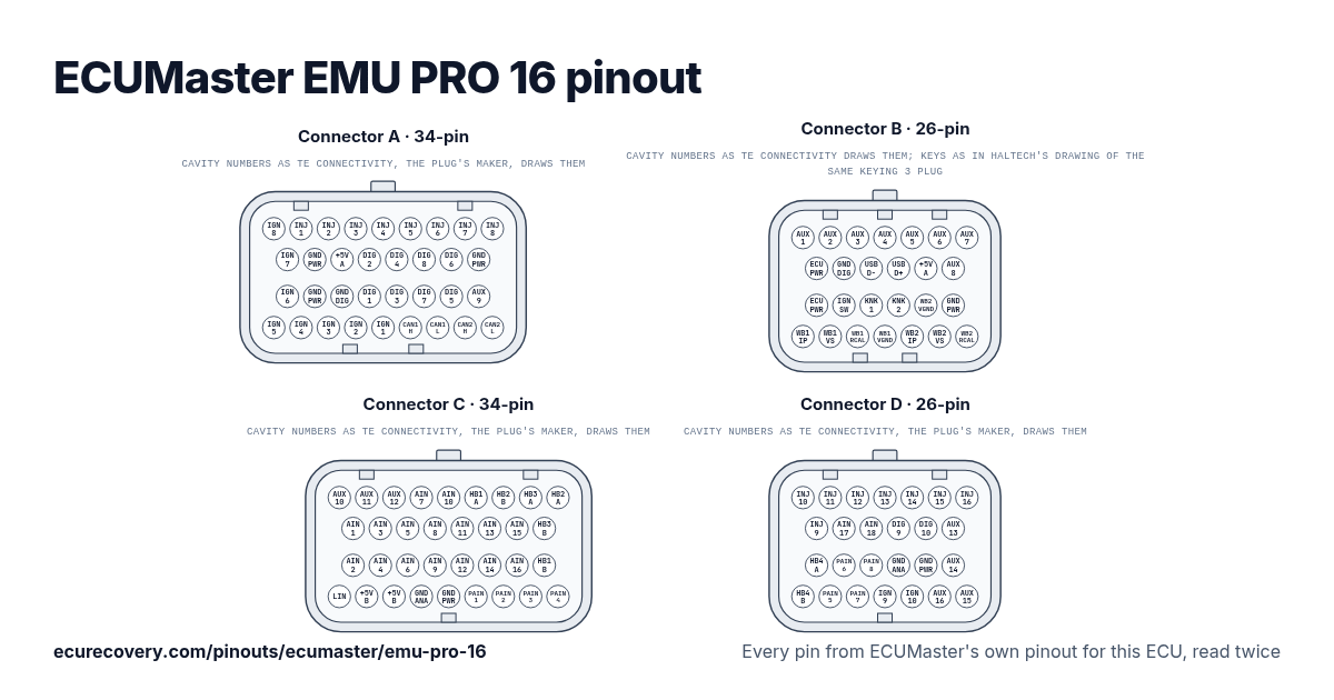
Cada pin de los conectores A (34 pines), B (26 pines), C (34 pines) y D (26 pines), con los nombres de pin de ECUMaster. Toca un pin para ver qué hace.
Cada pin del propio pinout de ECUMaster para esta ECU, leído dos vecesElige cualquier pin del dibujo o de la tabla para ver su función y los documentos donde se comprobó.
ECUMaster EMU PRO 16: pinout del conector A (34 pines)
Conector de acople: TE AMP Superseal 1.0 4-1437290-1
| Pin | Función | Nota de ECUMaster |
|---|---|---|
| A1 | Ignition 8 | Output for active or passive ignition coils. |
| A2 | Injector 1 | Output for high or low impedance injectors. |
| A3 | Injector 2 | Output for high or low impedance injectors. |
| A4 | Injector 3 | Output for high or low impedance injectors. |
| A5 | Injector 4 | Output for high or low impedance injectors. |
| A6 | Injector 5 | Output for high or low impedance injectors. |
| A7 | Injector 6 | Output for high or low impedance injectors. |
| A8 | Injector 7 | Output for high or low impedance injectors. |
| A9 | Injector 8 | Output for high or low impedance injectors. |
| A10 | Ignition 7 | Output for active or passive ignition coils. |
| A11 | Power GND | Power ground. |
| A12 | +5V source A | +5V sensor supply, source A. |
| A13 | Digital 2 | Digital signal input. |
| A14 | Digital 4 | Digital signal input. |
| A15 | Digital 8 | Digital signal input. |
| A16 | Digital 6 (turbo) | Digital signal input, can be used for turboshaft speed sensor. |
| A17 | Power GND | Power ground. |
| A18 | Ignition 6 | Output for active or passive ignition coils. |
| A19 | Power GND | Power ground. |
| A20 | Digital GND | Digital ground. |
| A21 | Digital 1 (crank) | Digital signal input, dedicated crankshaft sensor input. |
| A22 | Digital 3 | Digital signal input. |
| A23 | Digital 7 | Digital signal input. |
| A24 | Digital 5 (turbo) | Digital signal input, can be used for turboshaft speed sensor. |
| A25 | Auxiliary 9 | Output for auxiliary devices. |
| A26 | Ignition 5 | Output for active or passive ignition coils. |
| A27 | Ignition 4 | Output for active or passive ignition coils. |
| A28 | Ignition 3 | Output for active or passive ignition coils. |
| A29 | Ignition 2 | Output for active or passive ignition coils. |
| A30 | Ignition 1 | Output for active or passive ignition coils. |
| A31 | CAN 1 high (PC comm) | CAN bus, fixed 1Mbps, used for communication with PC and peripheral devices. |
| A32 | CAN 1 low (PC comm) | CAN bus, fixed 1Mbps, used for communication with PC and peripheral devices. |
| A33 | CAN 2 high | CAN bus, configurable speed, used for communication with peripheral devices. |
| A34 | CAN 2 low | CAN bus, configurable speed, used for communication with peripheral devices. |
ECUMaster EMU PRO 16: pinout del conector B (26 pines)
Conector de acople: TE AMP Superseal 1.0 1473416-1
| Pin | Función | Nota de ECUMaster |
|---|---|---|
| B1 | Auxiliary 1 (WBO heater) | Output for auxiliary devices, can be used as a WBO heater. |
| B2 | Auxiliary 2 (WBO heater) | Output for auxiliary devices, can be used as a WBO heater. |
| B3 | Auxiliary 3 (WBO heater) | Output for auxiliary devices, can be used as a WBO heater. |
| B4 | Auxiliary 4 (WBO heater) | Output for auxiliary devices, can be used as a WBO heater. |
| B5 | Auxiliary 5 | Output for auxiliary devices. |
| B6 | Auxiliary 6 | Output for auxiliary devices. |
| B7 | Auxiliary 7 | Output for auxiliary devices. |
| B8 | +12V supply | Power supply for the ECU and H-bridges. |
| B9 | Digital GND (flash drive) | Digital ground, recommended for flash drive connection. |
| B10 | USB D- (flash drive) | USB data pin for a flash drive, data logging. |
| B11 | USB D+ (flash drive) | USB data pin for a flash drive, data logging. |
| B12 | +5V source A (flash drive) | +5V sensor supply, source A, recommended for flash drive connection. |
| B13 | Auxiliary 8 | Output for auxiliary devices. |
| B14 | +12V supply | Power supply for the ECU and H-bridges. |
| B15 | +12V switched | +12V input to switch the ECU on or off. |
| B16 | Knock sensor 1 | Knock sensor input. |
| B17 | Knock sensor 2 | Knock sensor input. |
| B18 | WBO 2 VGND (LSU 4.9) | Wideband oxygen sensor input, LSU 4.9 Pin 2 (IPN / VM). |
| B19 | Power GND | Power ground. |
| B20 | WBO 1 IP (LSU 4.9) | Wideband oxygen sensor input, LSU 4.9 Pin 1 (APE / IP). |
| B21 | WBO 1 VS (LSU 4.9) | Wideband oxygen sensor input, LSU 4.9 Pin 6 (UN / RE). |
| B22 | WBO 1 RCAL (LSU 4.9) | Wideband oxygen sensor input, LSU 4.9 Pin 5 (RT / IA). |
| B23 | WBO 1 VGND (LSU 4.9) | Wideband oxygen sensor input, LSU 4.9 Pin 2 (IPN / VM). |
| B24 | WBO 2 IP (LSU 4.9) | Wideband oxygen sensor input, LSU 4.9 Pin 1 (APE / IP). |
| B25 | WBO 2 VS (LSU 4.9) | Wideband oxygen sensor input, LSU 4.9 Pin 6 (UN / RE). |
| B26 | WBO 2 RCAL (LSU 4.9) | Wideband oxygen sensor input, LSU 4.9 Pin 5 (RT / IA). |
ECUMaster EMU PRO 16: pinout del conector C (34 pines)
Conector de acople: TE AMP Superseal 1.0 4-1437290-0
| Pin | Función | Nota de ECUMaster |
|---|---|---|
| C1 | Auxiliary 10 | Output for auxiliary devices. |
| C2 | Auxiliary 11 | Output for auxiliary devices. |
| C3 | Auxiliary 12 | Output for auxiliary devices. |
| C4 | Analog 7 | Analog signal input. |
| C5 | Analog 10 (2k2 pull) | Analog signal input. |
| C6 | H-bridge 1A | H-bridge output. |
| C7 | H-bridge 2B | H-bridge output. |
| C8 | H-bridge 3A | H-bridge output. |
| C9 | H-bridge 2A | H-bridge output. |
| C10 | Analog 1 (MAP) | Analog signal input, dedicated MAP sensor input. |
| C11 | Analog 3 | Analog signal input. |
| C12 | Analog 5 | Analog signal input. |
| C13 | Analog 8 | Analog signal input. |
| C14 | Analog 11 (2k2 pull) | Analog signal input. |
| C15 | Analog 13 (1k pull) | Analog signal input. |
| C16 | Analog 15 (330R pull) | Analog signal input. |
| C17 | H-bridge 3B | H-bridge output. |
| C18 | Analog 2 | Analog signal input. |
| C19 | Analog 4 | Analog signal input. |
| C20 | Analog 6 | Analog signal input. |
| C21 | Analog 9 (2k2 pull) | Analog signal input. |
| C22 | Analog 12 (2k2 pull) | Analog signal input. |
| C23 | Analog 14 (1k pull) | Analog signal input. |
| C24 | Analog 16 (100R pull) | Analog signal input. |
| C25 | H-bridge 1B | H-bridge output. |
| C26 | LIN | LIN network. |
| C27 | +5V source B | +5V sensor supply, source B. |
| C28 | +5V source B | +5V sensor supply, source B. |
| C29 | Analog GND | Analog ground. |
| C30 | Power GND | Power ground. |
| C31 | Precision analog 1 | High precision analog input. |
| C32 | Precision analog 2 | High precision analog input. |
| C33 | Precision analog 3 | High precision analog input. |
| C34 | Precision analog 4 | High precision analog input. |
ECUMaster EMU PRO 16: pinout del conector D (26 pines)
Conector de acople: TE AMP Superseal 1.0 3-1437290-7
| Pin | Función | Nota de ECUMaster |
|---|---|---|
| D1 | Injector 10 | Output for high or low impedance injectors. |
| D2 | Injector 11 | Output for high or low impedance injectors. |
| D3 | Injector 12 | Output for high or low impedance injectors. |
| D4 | Injector 13 | Output for high or low impedance injectors. |
| D5 | Injector 14 | Output for high or low impedance injectors. |
| D6 | Injector 15 | Output for high or low impedance injectors. |
| D7 | Injector 16 | Output for high or low impedance injectors. |
| D8 | Injector 9 | Output for high or low impedance injectors. |
| D9 | Analog 17 | Analog signal input. |
| D10 | Analog 18 | Analog signal input. |
| D11 | Digital 9 / Analog 19 | Digital signal input or Analog signal input. |
| D12 | Digital 10 / Analog 20 | Digital signal input or Analog signal input. |
| D13 | Auxiliary 13 | Output for auxiliary devices. |
| D14 | H-bridge 4A | H-bridge output. |
| D15 | Precision analog 6 | High precision analog input. |
| D16 | Precision analog 8 | High precision analog input. |
| D17 | Analog GND | Analog ground. |
| D18 | Power GND | Power ground. |
| D19 | Auxiliary 14 | Output for auxiliary devices. |
| D20 | H-bridge 4B | H-bridge output. |
| D21 | Precision analog 5 | High precision analog input. |
| D22 | Precision analog 7 | High precision analog input. |
| D23 | Ignition 9 | Output for active or passive ignition coils. |
| D24 | Ignition 10 | Output for active or passive ignition coils. |
| D25 | Auxiliary 16 | Output for auxiliary devices. |
| D26 | Auxiliary 15 | Output for auxiliary devices. |
Pines de la ECUMaster EMU PRO 16 de un vistazo
- ¿Qué pines son CAN en la ECUMaster EMU PRO 16?
- CAN 1 high (PC comm): pin A31. CAN 1 low (PC comm): pin A32. CAN 2 high: pin A33. CAN 2 low: pin A34.
- ¿Qué pines son las salidas de inyectores en la ECUMaster EMU PRO 16?
- Injector 1: pin A2. Injector 2: pin A3. Injector 3: pin A4. Injector 4: pin A5. Injector 5: pin A6. Injector 6: pin A7. Injector 7: pin A8. Injector 8: pin A9. Injector 10: pin D1. Injector 11: pin D2. Injector 12: pin D3. Injector 13: pin D4. Injector 14: pin D5. Injector 15: pin D6. Injector 16: pin D7. Injector 9: pin D8.
- ¿Qué pines son las salidas de encendido en la ECUMaster EMU PRO 16?
- Ignition 8: pin A1. Ignition 7: pin A10. Ignition 6: pin A18. Ignition 5: pin A26. Ignition 4: pin A27. Ignition 3: pin A28. Ignition 2: pin A29. Ignition 1: pin A30. Ignition 9: pin D23. Ignition 10: pin D24.
- ¿Qué pines son masa en la ECUMaster EMU PRO 16?
- Power GND: pines A11, A17, A19, B19, C30, D18. Digital GND: pin A20. Digital GND (flash drive): pin B9. Analog GND: pines C29, D17.
- ¿Qué pines alimentan la ECUMaster EMU PRO 16?
- +12V supply: pines B8, B14. +12V switched: pin B15.
- ¿Qué pines alimentan los sensores en la ECUMaster EMU PRO 16?
- +5V source A: pin A12. +5V source A (flash drive): pin B12. +5V source B: pines C27, C28.
- ¿Qué pines son las conexiones del sensor de banda ancha en la ECUMaster EMU PRO 16?
- WBO 2 VGND (LSU 4.9): pin B18. WBO 1 IP (LSU 4.9): pin B20. WBO 1 VS (LSU 4.9): pin B21. WBO 1 RCAL (LSU 4.9): pin B22. WBO 1 VGND (LSU 4.9): pin B23. WBO 2 IP (LSU 4.9): pin B24. WBO 2 VS (LSU 4.9): pin B25. WBO 2 RCAL (LSU 4.9): pin B26.
Hoja de pinout de la ECUMaster EMU PRO 16
Una hoja imprimible con cada pin, hecha con los datos comprobados de esta página.
De dónde sale
Solo documentos del propio ECUMaster. Los nombres de los pines y las notas se muestran tal como los escribe ECUMaster, en inglés.
Pinout de ECUMaster para esta ECU
Guía de ECUMaster del EMU PRO 8, el mismo pin
Dibujo del conector: plano de cliente de TE Connectivity (solo para el dibujo)Tercero
Cómo lo comprobamos
- Partimos del documento de pinout de ECUMaster para esta ECU.
- Cada pin se lee otra vez en un segundo documento de ECUMaster: la hoja de pines compacta, el manual de usuario o, para los pines que son iguales en una ECU hermana, el pinout de esa ECU. Cuando ningún segundo documento indica un pin, lo leemos una segunda vez a ojo en el mismo pinout.
- Un pin solo se muestra cuando ambas lecturas dan la misma función. Los documentos de ECUMaster no indican colores de cable, así que no se muestran.
- Las notas son las propias descripciones de ECUMaster en su pinout.
ECU Recovery no está afiliada a ECUMaster. ECUMaster y sus nombres de producto son marcas de ECUMaster. Si tu arnés trae su propio diagrama, compara tu cableado con él.
¿Mapa bloqueado con contraseña?
Desbloqueamos mapas de Haltech, MaxxECU, LinkECU, Vi-PEC, ECUMaster, Emtron y FuelTech. Primero ves una prueba de tu propio archivo y solo pagas $159.99 si funciona.
Desbloquear un mapa